Soldering Pin Headers to Atmega32U4
Step 1 of the “Proposed Steps” from Converting a Wireless Trackball to Wired, is getting the Atmega32U4 working with the Arduino IDE. While the pin headers aren’t necessary for the Atmega board to talk to the Arduino IDE, they will be necessary to make it easier to get the board working with a simple switch.
It’s possible to purchase boards with the pin headers already attached, but then the board would be a bit more difficult to wire up later for use directly inside the EX-G housing.
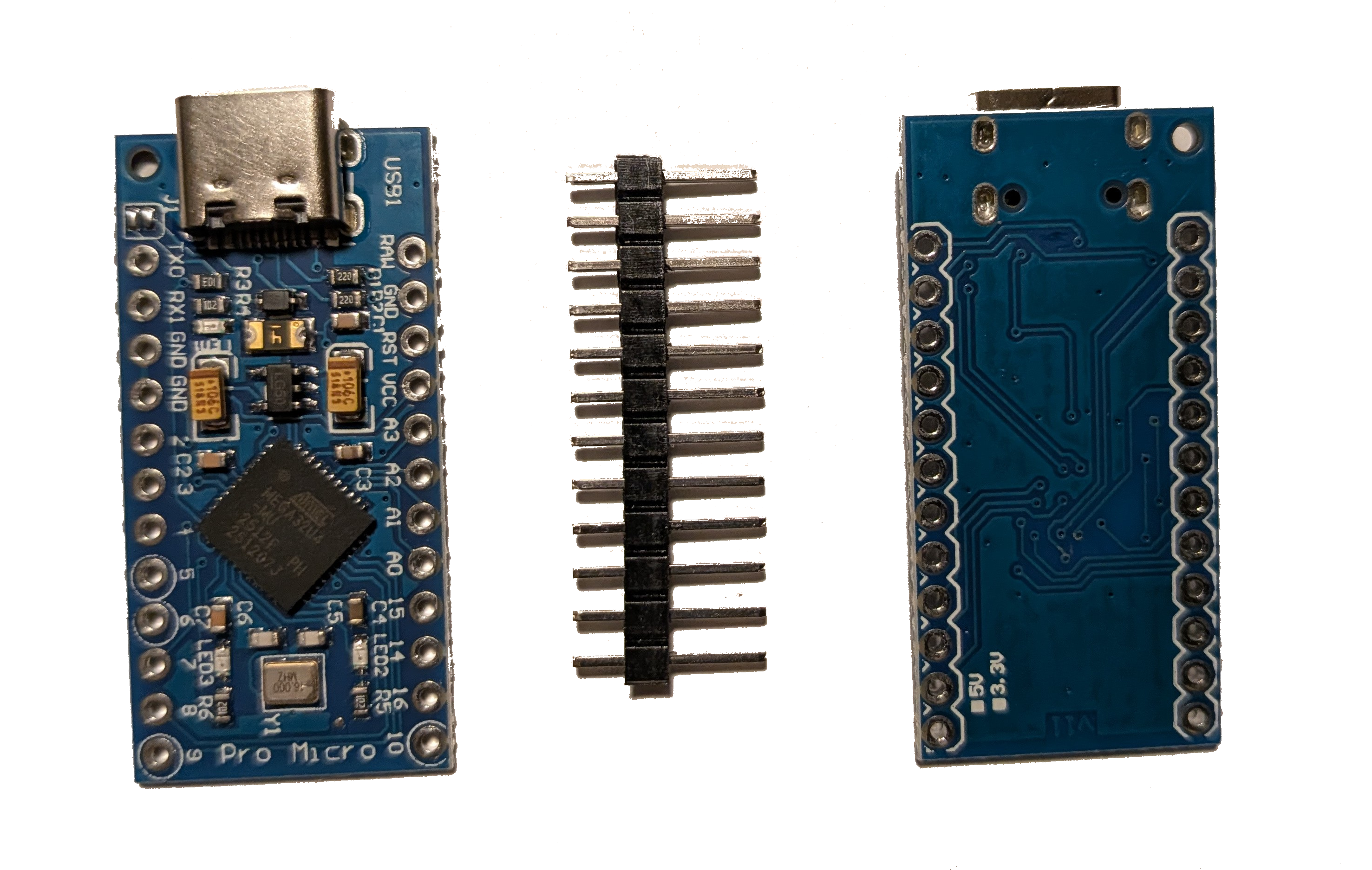
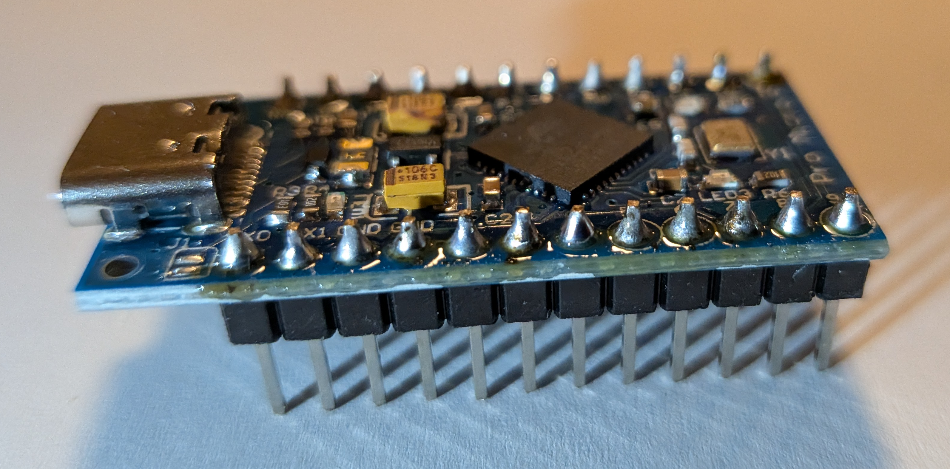
The Atmega board has two sides. One of the sides has all of the electronics on it, including some small LEDs as well as text near each hole. The other side is mostly blank. The blank side is the bottom of the board and it will be the side we put the headers through.
The pin headers have a short side and a long side. We want the short side to go into the Atmega board and keep the long side for plugging into a bread board.
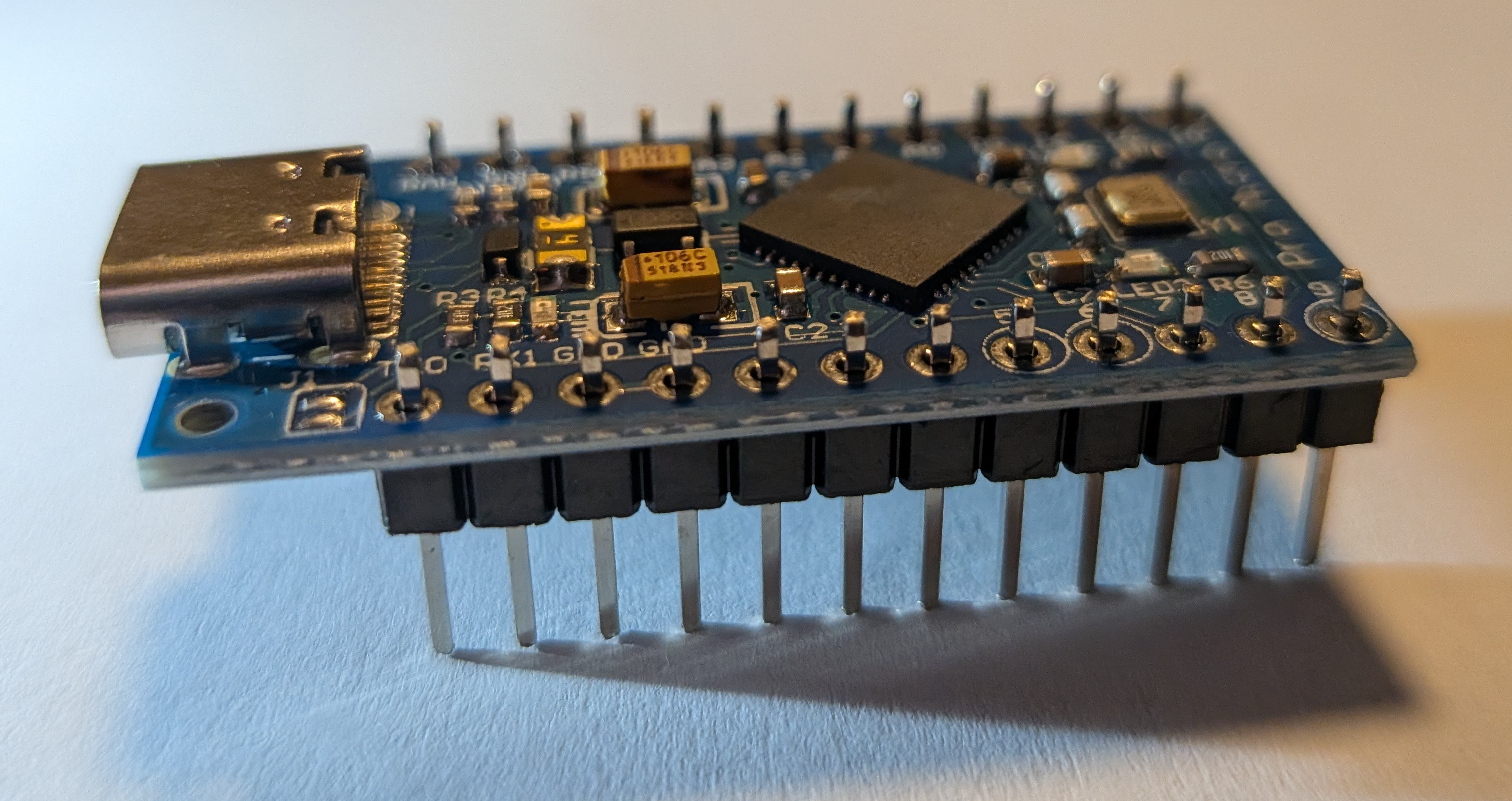
Below is an image of what it looks like with the pin headers inserted into the Atmega board. The top of the Atmega board is visible with the short side of the pin headers protruding through the top of the board.
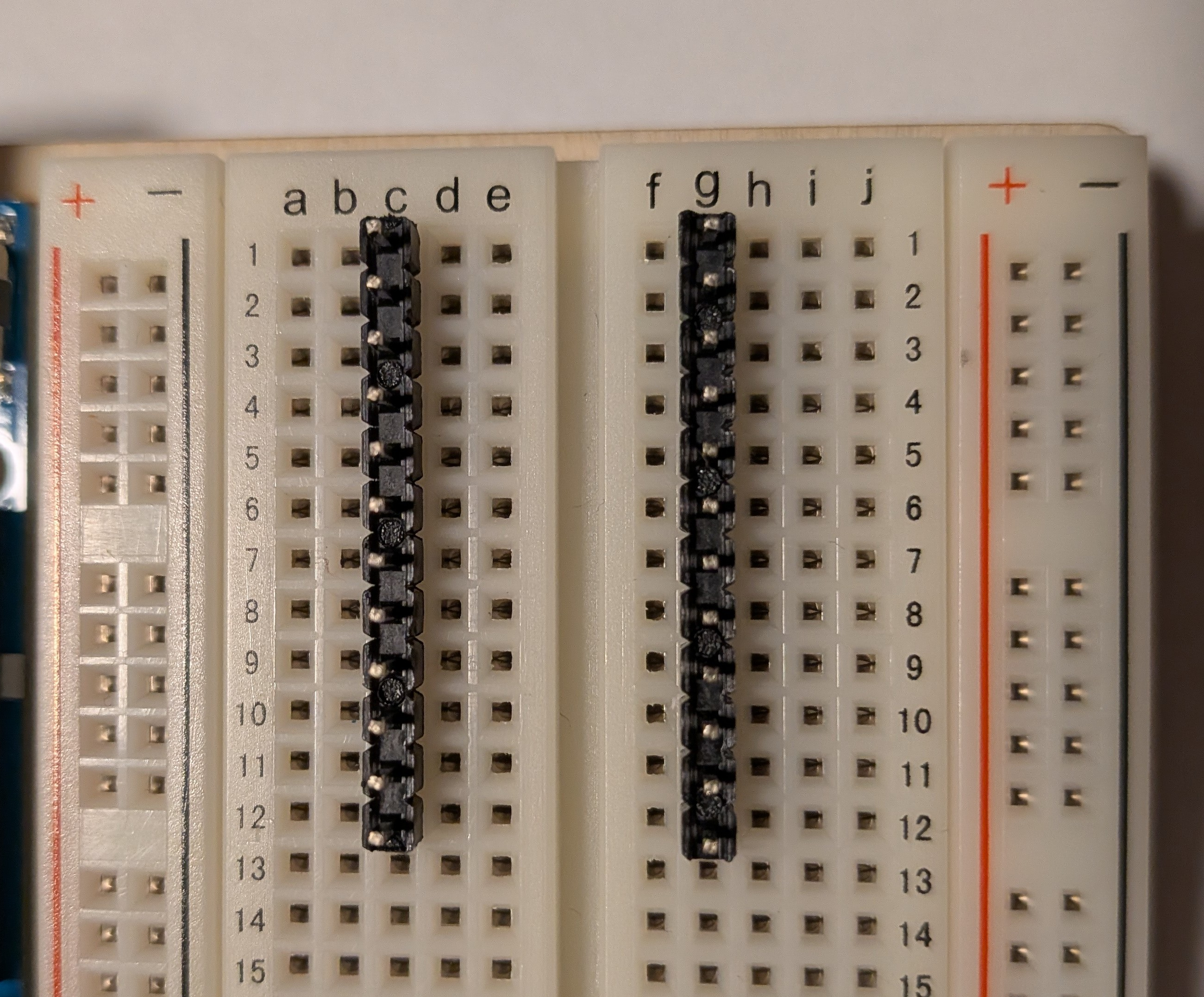
To ensure everything is aligned for soldering, I plugged the loosely assembled Atmega board with pin headers into the bread board.
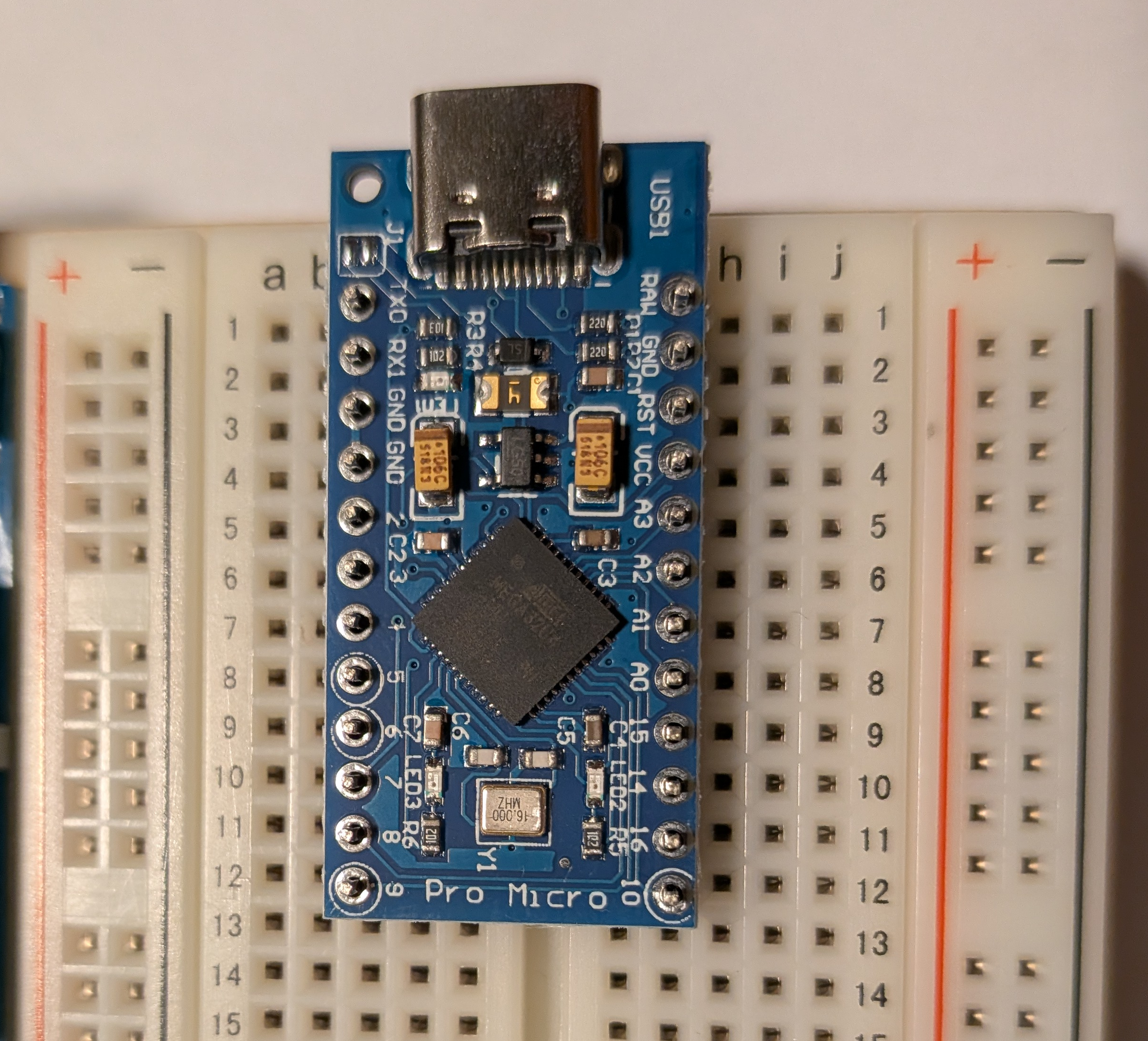
Initially when I tried to plug it in, I tried to keep it even in the center of the bread board. This didn’t work. The pin headers in the Atmega board end up being offset by one column of the bread board. The image below shows the left pin headers being three columns from the center, while the right pin headers are only two columns from the center.
With the Atmega board on the pin headers, in the bread board, I was able to solder the pin headers to the Atmega board and ensure everything was aligned correctly.
I’m not going to cover how to solder. At this point you may be feeling like I just pulled a draw the owl on you. In the previous post I said I had a soldering iron, I didn’t say I was proficient with it. Zooming in on a few of the soldered pins, they look almost like Hershey’s kisses, these are not good solder joints.
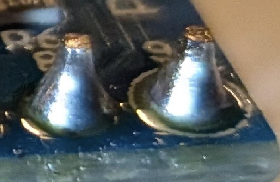
My understanding is that they look like Hershey’s kisses, because I didn’t have the Atmega board itself hot enough before I applied the solder. The solder melted on the pin, but then quickly cooled on the board instead of spreading out. There is also a bit too much solder.
Given my questionable solder skills, if you’re following along to do this yourself, you probably want to look elsewhere for soldering instructions.