Disassembling the EX-G Trackball
Looking back at the proposed steps from Converting a Wireless Trackball to Wired, Step 1 is complete. I’ve been able to get the Atmega development board to provide left click mouse events. While I haven’t programmed the right click, scroll wheel, or mouse movement events; I don’t think it will be too difficult to accomplish those later.
The next step on the list is trying to interpret the EX-G trackball sensor. With the first subtask of that being to disassemble the EX-G trackball. This post is going to cover the disassembly.
Remove Main Assembly Screws
The EX-G trackball housing is held together by screws through the bottom of the assembly. Looking at the bottom all of the screws are hidden.
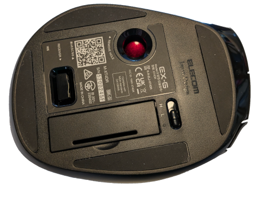
There are four rubber pads around the bottom. These are held on with some double sided sticky tape. Per some suggestions I found online, I used a heat gun to warm the pads up so that they could be pealed off with little to no damage. I placed the pealed off pads in a container to prevent dust, hair, etc from getting stuck on the exposed sticky sides. With the rubber pads removed the screws were now visible.
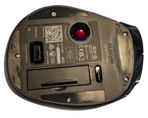
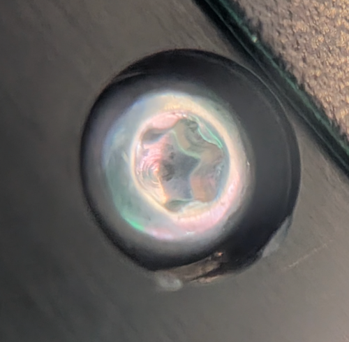
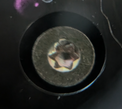
The screws have torx heads. They are size T6, with the exception of the one nearest the trackball. It is a T5 and it has a flat head while the others have more of a rounded head.
Example of one the T6 screws:
The flat headed T5 screw:
After removing all of these screws, I tried to separate the top and bottom halves of the EX-G. It did not want to separate. I could get create a small gap toward the front of the assembly, but nothing more. I found a youtube video which walks through the disassembly. At about 10:30 into the video the youtuber shows how there is another screw under the QR code sticker.
I felt around with my thumb, until I located the depression and then pierced the sticker to expose this screw. It was the same as the other T6 screws taken out earlier.
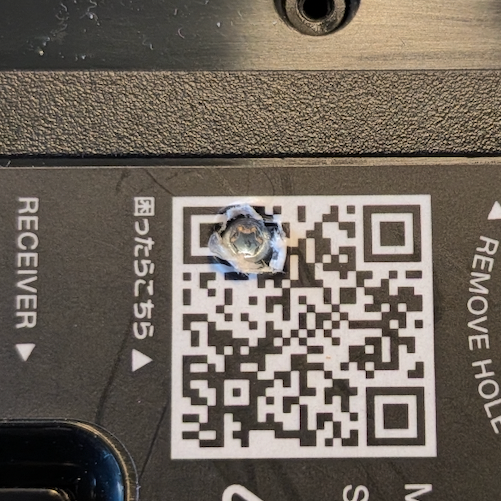
After removing this final screw the assembly came apart with very little force.
Inspecting the Guts
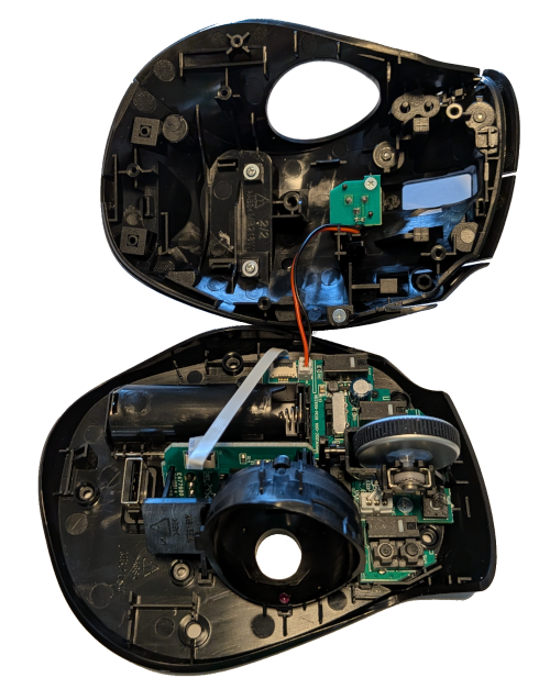
Looking at the bottom part of the trackball we can see that it contains a primary circuit board that the scroll wheel is attached to. The circuit board holds all the switches except for the low/high dpi toggle that is attached with the red and black wire from the upper shell.
Part of me was hoping the switches were attached to the case and were wired to the circuit board, so that I could just redirect the wires to the Atmega. It makes sense the manufacturer used the circuit board as part of the mechanical design to hold the switches as well as wire them directly. I will have to think on how I will eventually wire the switches to the Atmega board.
On starting this project I envisioned placing the USB connection out the front of the trackball, like most wired mice and trackballs. However looking at the placement of the circuit board in the housing it doesn’t look like there will be enough room. I’m thinking the USB connection will need to come out the right side, provided it doesn’t interfere with the trackball. This would allow the USB cable to be directed toward the keyboard and then have it go across the desk with the keyboard’s cable. Worst case the USB connection will come out the back and I may need to look for a 90 degree USB cable or connector.
The brains of the trackball can be seen underneath the scroll wheel.
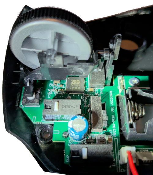
The trackball uses a Beken BK2535 processor. If I’m understanding the documentation correctly the wireless radio is built into the processor.
Inspecting PCB1
I wanted to get at the circuit board for a better inspection. To do this I removed:
- The two wire connector for the hi/low DPI toggle from the circuit board.
- The scroll wheel. It popped out with a little pressure and disconnecting the three wire connector.
- The trackball sensor. It was floating in the case, but required the disconnection of the 6 wire ribbon cable.
After that there were two Phillips head screws holding the board to bottom case. I had to work the battery wires out of the battery compartment during removal.
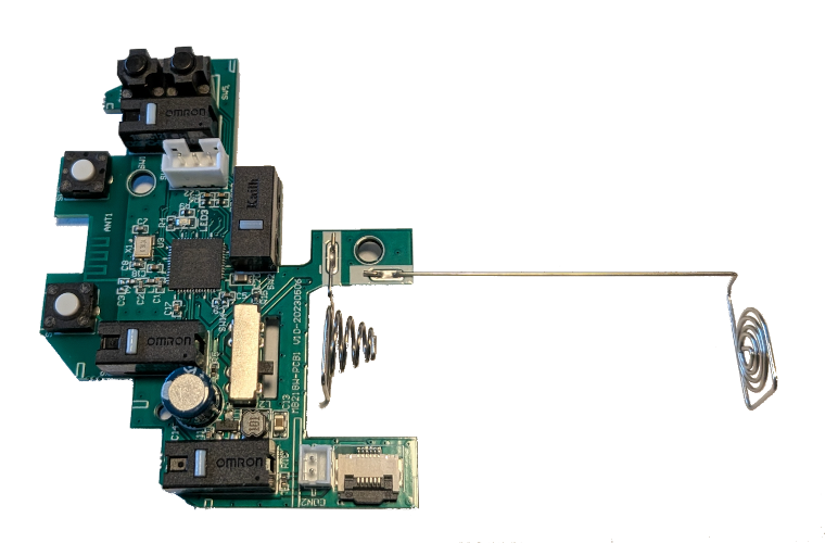
Looking closely at the board it has “MB218W-PCB1” printed on it. Pretty sure the “MB21BW” is likely some kind of part or model, while the “PCB1” is likely “Printed Circuit Board 1”.
I was curious about the trackball sensor and ribbon connector. Looking at the underside of the circuit board I could see four points near the ribbon cable connection.
- SD
- NCS
- SC
- T11
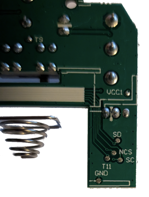
I have no idea yet what those abbreviations mean, but I’m hopeful that they might help in understanding how to get the trackball sensor working.
Inspecting the Trackball Sensor
The trackball housing assembly rests in two grooves in the bottom shell of the overall assembly. It’s held in place when the top and bottom shell are screwed together. With the ribbon cable removed from PCB1 it was a matter of picking up the trackball housing and looking at it.
Focusing on the circuit board that is attached to the trackball housing.
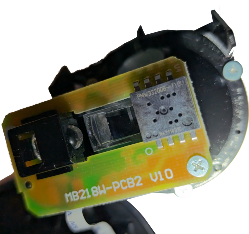
The circuit board has “MB218W-PCB2” printed on it, further supporting the idea that “MB21BW” is a part number and now “PCB2” is “Printed Circuit Board 2”.
Of particular note is the part number on what looks to be an IC chip, “PWM3320DB-TYDU”. Doing an internet search for this string quickly brings up an associated data sheet.
The PixArt Imaging PMW3320DB-TYDU is a small form factor entry-gaming optical navigation sensor.
With the sensor identified and a data sheet available this will hopefully make it easier to get the sensor working with the Atmega.
Inspecting the Scroll Wheel
The scroll wheel was popped out and disconnected when inspecting PCB1. No further disassembly was needed.
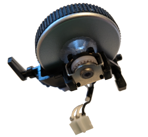
The scroll wheel seems to be fairly simple with three wires. One black and two white. I’m guessing the black is common and the white wires are for each direction. However, I don’t really know. I’ll need to look up scroll wheels I’m hoping they’re a fairly common interface.
Next Steps
The next step in the proposed steps from my initial plan is to get the trackball sensor working with the Atmega. I think I’m going to revise that. I hit a few hurdles getting a mouse click working. With that in mind, it may be better to focus on the scroll wheel first. It’s only three wires and is likely a simpler interface.
I’m chewing on how I want to handle the eventual wiring of the switches to the Atmega. I have a feeling that leaving the BK2535 processor on the board may result in interference with the switch events. When I connected a multimeter to the switch terminals to test conductivity, the meter initially registered a bit over 100Ω resistance, then it would go up to no conductivity. There are a number of capacitors on PCB1 these may be supporting hardware debounce, or it could be the BK2535 processor.