Getting the EX-G Scroll Wheel Working on Atmega32U4
In the previous post I took apart the EX-G and decided that getting the scroll wheel working with the Atmega32U4 development board would be the next step in converting the EX-G to a wired trackball.
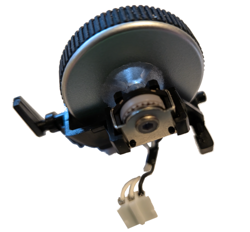
Looking again at the scroll wheel. It has three wires; one black and two white. My initial guess is that black is meant to be common, or ground, and each white wire would indicate the direction the wheel was turned.
Rotary Encoder
Searching the internet for “mouse scroll wheel arduino” brings up a lot of results with “rotary encoder”. Searching specifically for “arduino rotary encoder” provided some good references, such as:
- https://arduinogetstarted.com/tutorials/arduino-rotary-encoder
- https://lastminuteengineers.com/rotary-encoder-arduino-tutorial/
- http://www.multiwingspan.co.uk/arduino.php?page=rotary
A minimal rotary encoder has three wires:
CLKor “Clock”DTor “Data”GNDor “Ground”
The scroll wheel from the EX-G also has three wires, so I’m going to move forward assuming it’s a rotary encoder.
Many examples of rotary encoders have 5 terminals, with the extra two being +
and SW. These rotary encoders also contain a built in push button switch. The
scroll wheel does not have that functionality. The middle click button is a
separate switch on the EX-G circuit board that the scroll wheel assembly presses.
I’m not going to go into a description of how a rotary encoder works. I think the above linked articles due a very good job and I’m still coming up to speed with how they work. I will however go into the details of coding and wiring the wheel with the Atmega.
Connecting Scroll Wheel to Atmega
Revisiting the scroll wheel wires, I’m going to assume the black is the GND of
a rotary encoder. I was incorrect in my thought that each of the white wires was
for a different direction. I couldn’t find any distinguishing marks on the white
wires, the housing they connect to, or on the circuit board where the connector
goes. My understanding of rotary encoders is that which wire is CLK and which
is DT is more a convention than a hardware implementation. Given that I will
treat the middle wire as DT and the outside wire as CLK.
The plan is to wire:
- The black wire of the scroll wheel to an Atmega
GNDpin - The
DT, or middle white wire, to the Atmega IO pin2 - The
CLK, or outside white wire, to the Atmega IO pin3

The connector on the scroll wheel has a tighter spacing than my breadboard so I can’t utilize header pins. I’m going to insert wires directly into the connector holes and then put the wires into the bread board for the corresponding pins.

I couldn’t find a good scroll wheel pictorial so grabbed a generic rotary encoder pictorial from the Fritzing App.
Below is my initial attempt at coding this up. It took parts from the first two
rotary encoder references above. I added the Mouse.move() logic. The
references above were limited to printing out to the serial port. I used the
internal pull-up resistors. The reference examples did not and they didn’t seem
to use an external one either. I figure it should be mostly harmless to use the
internal pull-up resistors even if they aren’t needed.
#include <Mouse.h>

#define DT 2
#define CLK 3

int lastClkState = LOW;

void setup() {
  pinMode(DT, INPUT_PULLUP);
  pinMode(CLK, INPUT_PULLUP);

  lastClkState = digitalRead(CLK);
  Mouse.begin();
}

void loop() {

  int currentClkState = digitalRead(CLK);

  if (currentClkState != lastClkState && currentClkState == HIGH) {
    int dtState = digitalRead(DT);
    if (dtState == currentClkState) {
      Mouse.move(1, 0, 1);
    } else {
      Mouse.move(-1, 0, 1);
    }
    lastClkState = currentClkState;
  }
}
Trying to compile this using the Arduino CLI resulted in the following failure:
scroll_wheel.ino:1:10: fatal error: Mouse.h: No such file or directory
 #include <Mouse.h>
          ^~~~~~~~~
compilation terminated.
I had moved over to using the Arduino CLI in
Developing Arduino Sketches with Neovim.
In this I had uploaded a simple sketch, but hadn’t done a sketch involving the
mouse yet. While the Arduino IDE installs some common libraries local to its
environment, the Arduino CLI does not install these libraries. The missing
header was remedied by installing the Mouse library.
arduino-cli lib install Mouse
Once the code was compiling, uploading the code resulted in nothing happening
when moving the scroll wheel. I tried directly grounding and ungrounding the
CLK pin to no avail. I then placed some serial print statements in the code to
help debug.
The code updated to have serial print statements
#include <Mouse.h>

#define DT 2
#define CLK 3

int lastClkState = LOW;

void setup() {
  pinMode(DT, INPUT_PULLUP);
  pinMode(CLK, INPUT_PULLUP);

  lastClkState = digitalRead(CLK);
  Mouse.begin();
  Serial.begin(9600);
}

void loop() {

  int currentClkState = digitalRead(CLK);

  if (currentClkState != lastClkState && currentClkState == HIGH) {
    int dtState = digitalRead(DT);
    Serial.print("Clk State: ");
    Serial.println(currentClkState);
    Serial.print("DT State: ");
    Serial.println(dtState);
    if (dtState == currentClkState) {
      Mouse.move(1, 0, 1);
    } else {
      Mouse.move(-1, 0, 1);
    }
  lastClkState = currentClkState;
  }
}
The print statements would result in outputting the pin states once when moving the scroll wheel. This printing would only happen sometimes after connecting and disconnecting the board from my computer. When it printed after a reconnect and movement of the wheel it was always one set of states.
Clk State: 1
DT State: 1
Looking closer at the code I realized I had made a mistake. When I ported the
logic over from the rotary encoder examples, I had put the update of
lastClkState inside the if block. My thinking was the if block was only being
entered when the states differed, if (currentClkState != lastClkState ....
However, I forgot about the other part of the condition that checked for the
current state being HIGH. This means once the lastClkState was set HIGH
the if condition would never be entered again. The fix was to move the update
outside of the if condition.
Moving lastClkState update location
#include <Mouse.h>

#define DT 2
#define CLK 3

int lastClkState = LOW;

void setup() {
  pinMode(DT, INPUT_PULLUP);
  pinMode(CLK, INPUT_PULLUP);

  lastClkState = digitalRead(CLK);
  Mouse.begin();
}

void loop() {

  int currentClkState = digitalRead(CLK);

  if (currentClkState != lastClkState && currentClkState == HIGH) {
    int dtState = digitalRead(DT);
    if (dtState == currentClkState) {
      Mouse.move(1, 0, 1);
    } else {
      Mouse.move(-1, 0, 1);
    }
  }
  lastClkState = currentClkState;
}
After compiling and uploading this change the mouse scroll wheel scrolled, but only up.
I had looked at the
Mouse.move() documentation
and felt it was a bit sparse. Looking at the signature:
void move(signed char x, signed char y, signed char wheel = 0);
I interpreted wheel to be a flag indicating that x and y apply either to
the cursor or to the wheel. I recalled running across people on the internet
asking how to do side scrolling with Arduino’s built in mouse library and
thinking to myself, it seems easy with this interface.
Revisiting the Mouse.move() documentation I saw:
wheel: amount to move scroll wheel. Allowed data types: signed char.
With this I realized that wheel is not a flag, but an amount. Apparently I
initially glossed over the documentation I thought was sparse. So I updated
the code to pass 1 to the wheel argument for one direction and -1 for
the other direction. Always passing 0, 0 for both x and y arguments.
Fix for scroll wheel direction
#include <Mouse.h>

#define DT 2
#define CLK 3

int lastClkState = LOW;

void setup() {
  pinMode(DT, INPUT_PULLUP);
  pinMode(CLK, INPUT_PULLUP);

  lastClkState = digitalRead(CLK);
  Mouse.begin();
}

void loop() {

  int currentClkState = digitalRead(CLK);

  if (currentClkState != lastClkState && currentClkState == HIGH) {
    int dtState = digitalRead(DT);
    if (dtState == currentClkState) {
      Mouse.move(0, 0, 1);
    } else {
      Mouse.move(0, 0, -1);
    }
  }
  lastClkState = currentClkState;
}
I compiled, uploaded, and crossed fingers. The scroll wheel still only scrolls up.
Fortunately I didn’t chase my tail too long here. I was using some jumper wires
to connect the bread board to the scroll wheel. I pulled these wires out of the
scroll wheel and started touching them together to mimic the wheel turning.
Touching only the CLK wire to the GND would result in scrolling up. If I
touched the DT wire to the GND and then touch the CLK to GND I could get
a scroll down!! The jumper wires were a little bit larger than ideal and the
DT wire was not making full contact in the scroll wheel connector. Reworking
this physical connection, I was able to get the mouse wheel to do a scroll up and a
scroll down.