Navigating the PWM3320DB-TYDU Data Sheet
Disassembling the EX-G Trackball revealed that the optical sensor used in the EX-G trackball was the PWM3320DB-TYDU. There is a data sheet that can be found on the internet for the PWM3320DB-TYDU.
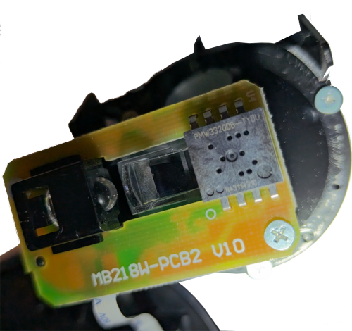
As a reminder here is the trackball housing showing the sensor in a circuit board. To the left of the sensor is an LED.
The first page of the data sheet has the “Key Specification” table. This piqued my interest:
| Supply Voltage | 2.1-3.4V |
| Interface | 3-wired SPI Max clock speed: 1MHz |
| Tracking Speed | Up to 80ips |
| Acceleration | Up to 20g |
| CPI Resolution | Up to 3500cpi with 250cpi/step |
| Frame Rate | Max: 5300 fps (frames per second) |
| Operating Current | VDD=2.2V Run Avg : 7.9mA REST1 : 1.4mA REST2 : 0.090mA Power down : 15uA *Including 16mA LED current |
| Package | 8-pin DIP |
There were a few acronyms in the specification that I was unfamiliar with:
- SPI: Serial Peripheral Interface
- ips: Inches per second
- g: acceleration due to (Earth’s) gravity
- CPI: Counts Per Inch
The second page of the sheet gives us a nice visual of the sensor terminals. The visual is recreated here using schemdraw

SDIO, SCLK, and NCS are the three wires for the SPI.
GND and VDD are the ground and power supply to the sensor.
REG I’m unsure what this is, it’s listed as an output so I’m hopeful it’s
wired up as needed in the pre-existing circuit board.
LED This is listed as an input, but I’m thinking that might be a misprint and
it’s an output to the LED. Later I noticed in the schematic on page 5 that it
shows this LED pin connected to one end of an LED and the other end connected
to the voltage supply that feeds VDD, further confirming this behavior.
MOTION, in Table 1 of the data sheet says:
Motion Interrupt Output (Active Low)
I’m interpreting this to mean that MOTION provides an interrupt signal to the
controller. When the sensor sees movement it triggers the interrupt for the
controller to be able to come back and ask for the movement details.
The next few pages of the data sheet are physical measurements and suggested wiring diagrams. The physical measurements didn’t seem useful since I’m reworking something that has already chosen the sensor and was able to fit the sensor in the housing. The wiring diagrams looked like full examples of a mouse with three click buttons and scroll wheel (called Z-Encoder). The wiring diagrams may become helpful later, but I’m thinking I may be able to leverage a lot of how it was already wired.
On page 7 we get to Table 3: Recommended Operating Conditions. Two entries in that table which stood out were the Power Supply Voltage (VDD) and the Serial Port Clock Frequency.
The voltage had a range of 2.1V to 3.4V. I realized I never checked what voltage the Atmega board I got was. Looking at the sparkfun Pro Micro there are two variants a 3.3V and a 5V. If I have a 5V board then I will need some way to convert the voltage to the acceptable range. Doing a bit of digging, and also looking at the schematics in the data sheet, it appears the common name for this voltage conversion is a “Level Shifter”.
The serial port clock frequency stood out, as it will be needed to correctly configure the SPI communication. It doesn’t provide a range, just a max at 50% duty cycle. Since I won’t be gaming with this trackball, I’m guesstimating that I won’t exceed the 50% duty cycle and can comfortable run it at the max speed.
The next page had some electrical specifications, but it looked more like power consumption values and didn’t seem to matter for my wired use case.
The last page of the data sheet lists the registers available via the serial interface. The register table shows which ones are readable and which ones are writeable, as well as the default values. The default values are in hex, with no indication of what the values really mean.
Some registers that stood out to me:
DELTA_XandDELTA_Y, likely contain the mouse movement.RESOLUTION, guessing this allows setting the CPI. With a default value of0x80, figuring this might be close to \(\frac{3500cpi}{2}\) or \(1750cpi\).AXIS_CONTROLI’m hoping the manufacturer lined up the sensor based on thumb movement, but I was considering the possibility of needing to do a rotation before sending theMouse.move()events. With this register it looks like any rotation correction could be done in hardware.PERFORMANCEI’m wondering if this is a way to set the “Programmable power modes” that’s mentioned in the general description on the first page of the data sheet.BURST_MOTIONandBURST_READ_FIRST. WithBURST_READ_FIRSTbeing set to default to0x03which is theDELTA_Xregister, I’m thinking these allow for getting data in a streaming fashion, instead of asking for individual registers.
There isn’t much detail on how to read or write the registers or how to interpret the values. I’m hoping that digging into SPI might shed light into how to read and write the registers.
I plan to dig into SPI and how to communicate with the PWM3320DB-TYDU sensor in the next post.