Using Arduino UNO as logic analyzer
Building on my investigation in the previous post, I wanted to be able to see what messages the EX-G trackball controller was sending to the PMW3320DB-TYDU mouse sensor. I was pretty sure a logic analyzer would allow me to investigate the communication. Not having a dedicated logic analyzer, I attempted to use the Arduino UNO that I had available as a logic analyzer.
Logic Analyzer libraries
I found two possibilities for using the Arduino as a logic analyzer:
- A logic analyzer library on Github, https://github.com/pschatzmann/logic-analyzer
- The LogicAnalyzer library available via the Arduino Library Reference
I wanted to go with the library I found on Github, because it mentioned trying to improve on Arduino LogicAnalyzer library and its example looked pretty easy to use. However, reading further through the documentation I saw that for AVR processors it only supported 110Khz and 500 samples. With the PMW3320DB-TYDU supporting up to 1Mhz the 110Khz didn’t seem like it would have the resolution necessary to capture the messages. 500 samples is also a very small window to try and get the events to happen and then record them. If I did the math correctly it would only have a ~4ms window. With all that in mind I chose to go with the Arduino LogicAnalyzer library.
The Arduino LogicAnalyzer library provides an example sketch, logic_analyzer_sigrok.ino, that works with the PulseView GUI tool. To be honest, that example sketch seemed pretty complex compared to the example from https://github.com/pschatzmann/logic-analyzer. I figured I would try it out and see what happens. It compiled and uploaded to the Arduino UNO with no problem.
PulseView
In order to visualize the data, I would need some kind of GUI. A common one that people seem to use is PulseView.
The download page has a heading:
Nightly builds (recommended, always up-to-date)
I downloaded the nightly version for Mac and attempted to run it. It didn’t open any graphical window. I had to go into Activity Monitor and force kill it.
I decided to grab the most recent release, 0.4.2, for Mac. I was curious when this version was released, so did some digging through their repo. pulsview-0.4.2 appears to have been released in March of 2020. While this is almost 6 years ago, logic analyzers have been around for a while so it could be that it doesn’t need many changes. At the same time, Mac OS has changed a bit since then i.e. the Intel to Arm transition, so fingers crossed.
This version did run. It got initially blocked by GateKeeper, but it’s older software and open source isn’t convenient to get Apple code signing, so I went into the security settings and allowed PulseView to run.
Connecting PulseView to the Arduino
For connecting PulseView to the Arduino I followed a slightly modified version of the steps in the logic analyzer library that I didn’t use:
- Select “Connect to a Device”:
- Choose the Driver: Openbentch Logic Sniffer & SUMP Compatibles
- Choose the Interface:
- Serial Port
- Port that the Arduino Uno shows up on
- Choose 115200 baud, to align with the
Serial.begin(115200)from the logic_analyzer_sigrok.ino
- Click on “Scan for Devices using driver above” button
- Select the Device - “AGLAv0 with 6 channels”
These steps need to be performed with the Arduino Uno flashed with the logic analyzer sketch and currently plugged into the computer.
Using the Logic Analyzer
During the disassembly of the EX-G trackball I noted some points at the underside of where the PMW3320DB-TYDU ribbon attaches to the circuit board:
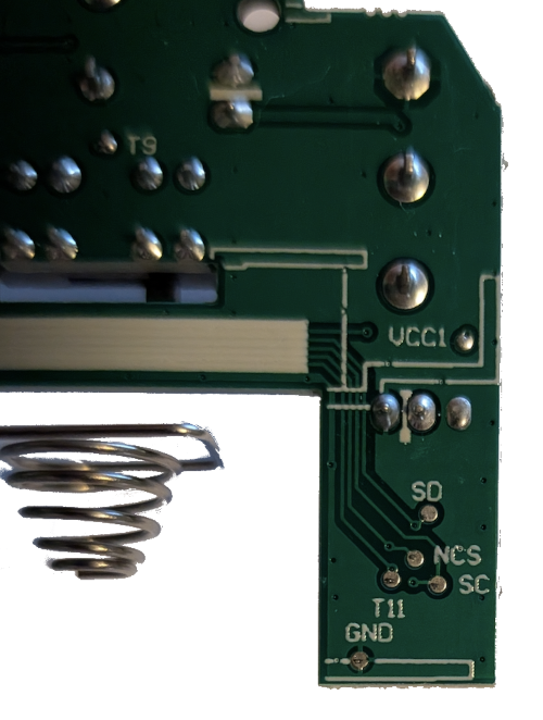
I previously didn’t know what some of the points were for. After learning about SPI, I can say what these points likely represent
- SD: The SPI data line
- NCS: SPI chip select. It seems
Nmeans “not chip select” indicating that when this line goes low the chip is selected. - SC: The SPI clock line
The logic analyzer sketch uses Arduino pins 8-13. I was sure I couldn’t couldn’t
attach pin 8 to SD and things would work. The logic analyzer needed some kind
of reference to know when SD is low or high. I wasn’t sure if I should attach
pin 9 to the ground on the EX-G circuit board. Looking in the logic analyzer
sketch there didn’t seem to be good instructions on how to actually use it.
After doing some internet searching for a bit, I ran across http://www.microtan.ukpc.net/Tools/LA_Linux.html. Under the heading “Using Logic Sniffer” it had this instruction:
Connect ground wire from Arduino pin GND to equipment ground.
With a battery powering the EX-G and all of its electrical components connected
back up. I connected the Arduino GND to the GND on the EX-G circuit board. I
then connected pin 8 from the Arduino to the SD point on the EX-G circuit
board. I then clicked on the “Run” button in PulseView. The run lasted a few
seconds and stopped. It showed a solid low line for channel 0. For my next test
I started continually moving the trackball, with everything still connected, and
hit the “Run” button. Still a solid low line for channel 0. I retried the
previous tests using Pin 9, which is channel 1 in PulseView, still solid low
line.
I realized the Arduino is a 5V system meaning it’s looking for a 5V high line.
While the PMW3320DB-TYDU is in a ?V system. At this point I realized I didn’t
know what it was operating at as part of the EX-G. From the
data sheet
the operating range is 2.1V to 3.4V. I grabbed my multimeter and checked between
GND and NCS, giving me 2.2V. I chose NCS since it is high until the chip
was selected, so as long as I didn’t touch the trackball it should be high while
measuring. Doing some digging online, Arduino’s don’t register a digital high
until ~3V. This means the 2.2V is too low to register for the Arduino.
This means I would need a level shifter (some thing I recently learned about) to get the Arduino to see the change. Web searches for “arduino uno level shifter from 2.2v to 5v” kept coming back suggesting getting a dedicated level shifter board. It was getting late, so I decided to punt it over to the AI overlords. AI suggested using a circuit with a transistor to step up the voltage. I asked AI if the transistor could handle 1Mhz transitions and it assured me it could. Whether this is true, I don’t really know.

Wiring this up to the Arduino looked something like:

Arduino Image Source, CC-BY-SA-3.0.
After wiring this up, I did run across https://docs.arduino.cc/learn/microcontrollers/5v-3v3/#stepping-up which covers a similar approach to a level shifter.
Retrying the previous steps where I connected SDIO from the bread board to the
EX-G SD point, I now was getting a solid logical low when not touching the
trackball. If I manipulated the trackball when pressing the “Run” button, I
could see the line go high, but it was a solid high line, no jumps or cycling of
the line to indicate low and high data bits.
Due to:
- having to go through the level up shifter
- physical difficulty trying to simultaneously
- manipulate the trackball
- hold the wires on the correct terminals of the EX-G circuit board
- click the “Run” button in PulseView
- short capture length of PulseView
- only getting constant logic low or logic high
I decided to chalk the Arduino logic analyzer up as a failure and pivot. Looking to see what inexpensive logic analyzers were out there. I decided to order the Lonely Binary Logic Analyzer. This one was chosen as it was inexpensive and it works with Saleae Logic Pro 2.
It may have been the limitations of the Arduino as a logic analyzer, but I wasn’t very impressed with using PulseView and want to be able to try something else. Since Saleae sells some more expensive logic analyzers, https://saleae.com/logic, I’m hoping their GUI is a better experience.
Next: get the Lonely Binary logic analyzer and re-attempt capturing SPI data between the EX-G and sensor.
PS
I did not capture screenshots of using PulseView or more detailed info of how I used it since it didn’t work out for me. While I can understand that having the details could help someone potentially find out where I may have gone wrong if the tools really could work for my use case, I didn’t want to sink too much time into a path that wasn’t getting me anywhere.