Using Arduino SPI library
After moving over to the esp32c6 development board, I felt the next step was to get the esp32c6 talking SPI.
The plan was to get the esp32c6 to send two bytes via SPI. I would verify the correctness of the message by capturing it with the logic analyzer. The reason for two bytes is that’s the common message the PMW3200DB-TYDU uses for SPI.
Programming SPI
The first thing I did was to write up a simple Arduino sketch that would write out the two bytes. The Arduino libraries come with an SPI library, which I used.
The SPI library is mentioned on Arduino’s page discussing SPI communication https://docs.arduino.cc/learn/communication/spi/. That page provides a link to the SPI library documentation, https://www.arduino.cc/en/reference/SPI, but the link is dead. I pieced together my initial attempt from the first Arduino link as well as a good write up I found, The Arduino SPI library.
#include <SPI.h>

void setup() {
  SPI.begin();
}

void loop() {
  SPISettings settings = SPISettings(1, SPI_MSBFIRST, SPI_MODE3);
  SPI.beginTransaction(settings);
  SPI.transfer(0x01);
  SPI.transfer(0x22);
  SPI.endTransaction();
  delay(1000);
}
I used begin() with no arguments, which means it should use the default pins
for the SPI lines.
Based on what I took away reading through the “The Arduino SPI Library”, the
clock speed specified isn’t exact. The system will choose an appropriate speed
based on the requested speed and the actual hardware capabilities. I chose 1
to have the clock run as slowly as possible, thinking I might hook the signal up
to an LED to better visualize what’s happening.
SPI_MSBFIRST and SPI_MODE3 were chosen based on the successful use of them
when snooping on the
pmw3320DB-TYDU SPI.
Hopefully the code isn’t too hard to follow.
- Start an SPI message with
beginTransaction() - Send an arbitrary byte of
0x01 - Send a second arbitrary byte of
0x22 - End the SPI message with
endTransaction() - Repeat every second
The code compiled and uploaded to the esp32c6 board without issue.
arduino-cli compile -u -p /dev/cu.usbmodem1301 --fqbn esp32:esp32:XIAO_ESP32C6
But did it work?
Connecting esp32c6 to Logic Analyzer
The next thing I did was connect the esp32c6 development board to the logic analyzer. I looked at the diagrams for the esp32c6 board from https://wiki.seeedstudio.com/xiao_esp32c6_getting_started/. The diagram showed which pins on the board correspond to which SPI functions.
I noticed there was no chip select pin shown in the diagram. In order to figure
out what the pin was for this, I assigned a dummy variable to the value of
MOSI and then jumped to its definition.
int foo = MOSI;
In order for the jump to definition to work, the SPI.h header needs to be
included. Something to watch out for, is to ensure the correct hardware is
chosen when jumping to definition. Each hardware defines its own values for
MOSI and the other SPI pins.
Jumping to definition led me to the pins_arduino.h header file, which has:
static const uint8_t SS = 21;
static const uint8_t MOSI = 18;
static const uint8_t MISO = 20;
static const uint8_t SCK = 19;
In that header file, as well as the diagram from Seeed Studio, there is a
mapping of the pin numbers to the D# pin numbers that the Seeed Studio diagram uses.
static const uint8_t D3 = 21;
//...
static const uint8_t D8 = 19;
static const uint8_t D9 = 20;
static const uint8_t D10 = 18;
Consolidating the mapping into one table:
| Function | Board pin | Code(chip) Pin |
|---|---|---|
| MOSI | D10 | 18 |
| MISO | D9 | 20 |
| SCK | D8 | 19 |
| SS | D3 | 21 |
I connected the esp32c6 to one end of the bread board and the logic analyzer
with bread board connector to the other end. I connected the esp32c6 ground to
the GND of the logic analyzer. I then connected the MOSI, SCK, and the
SS pins of esp32c6 to separate channels of the logic analyzer.
| esp32c6 pin | logic analyzer pin |
|---|---|
| D10 | 0 |
| D8 | 1 |
| D3 | 2 |
The hook up was similar to the below pictorial:

Seeed Studio esp32c6 Image Source, CC-BY-SA-4.0.
Capturing SPI Traffic
I used the Saleae Logic Pro 2 software to capture the SPI traffic. Since the implementation I wrote used a 1 second periodic loop, I set the Logic Pro 2 to use a timer capture of three seconds.
I configured the Logic Pro 2 SPI data analysis to match the connections made above.
- channel 0 was MOSI
- channel 1 was clock
- channel 2 was enable
- channel 4 was MISO
MISO didn’t matter where it went as I wasn’t using it. I hid all channels
except 0, 1, and 2.
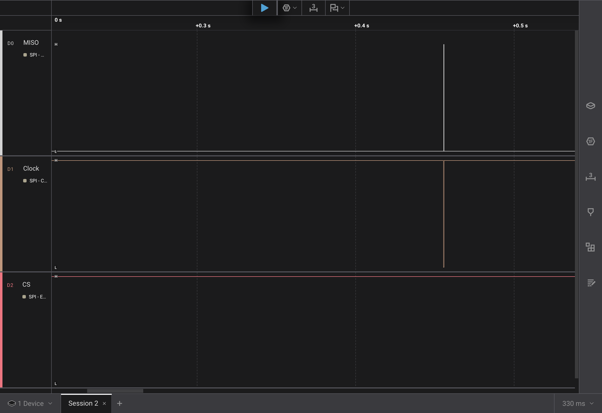
With everything hooked up I recorded a capture. I could see three instances, one a second, of the following:
Zooming I could see

A couple of issues stand out right away with what was captured:
- The
CSnever went low - The clock only showed two dips, not 8 per byte
Debugging the Clock
Looking at the way the MOSI line and the clock lines up, it made me think that
I might be capturing the chip select on the clock channel. I re-scrutinized the
hardware connections and the pin to function mappings. These all seemed correct.
I tried to be explicit in the begin function and specify each pin, using it’s define. This didn’t fix the issue.
void setup() {
  SPI.begin(SCK, MISO, MOSI, SS);
}
I tried rewiring everything so that all connections were on one side of the logic board’s connector. Still same result running a new recording.
I decided to changed the clock frequency to the 1,000,000 MHz that the PMW3320DB-TYDU supports.
SPISettings settings = SPISettings(1000000, SPI_MSBFIRST, SPI_MODE3);
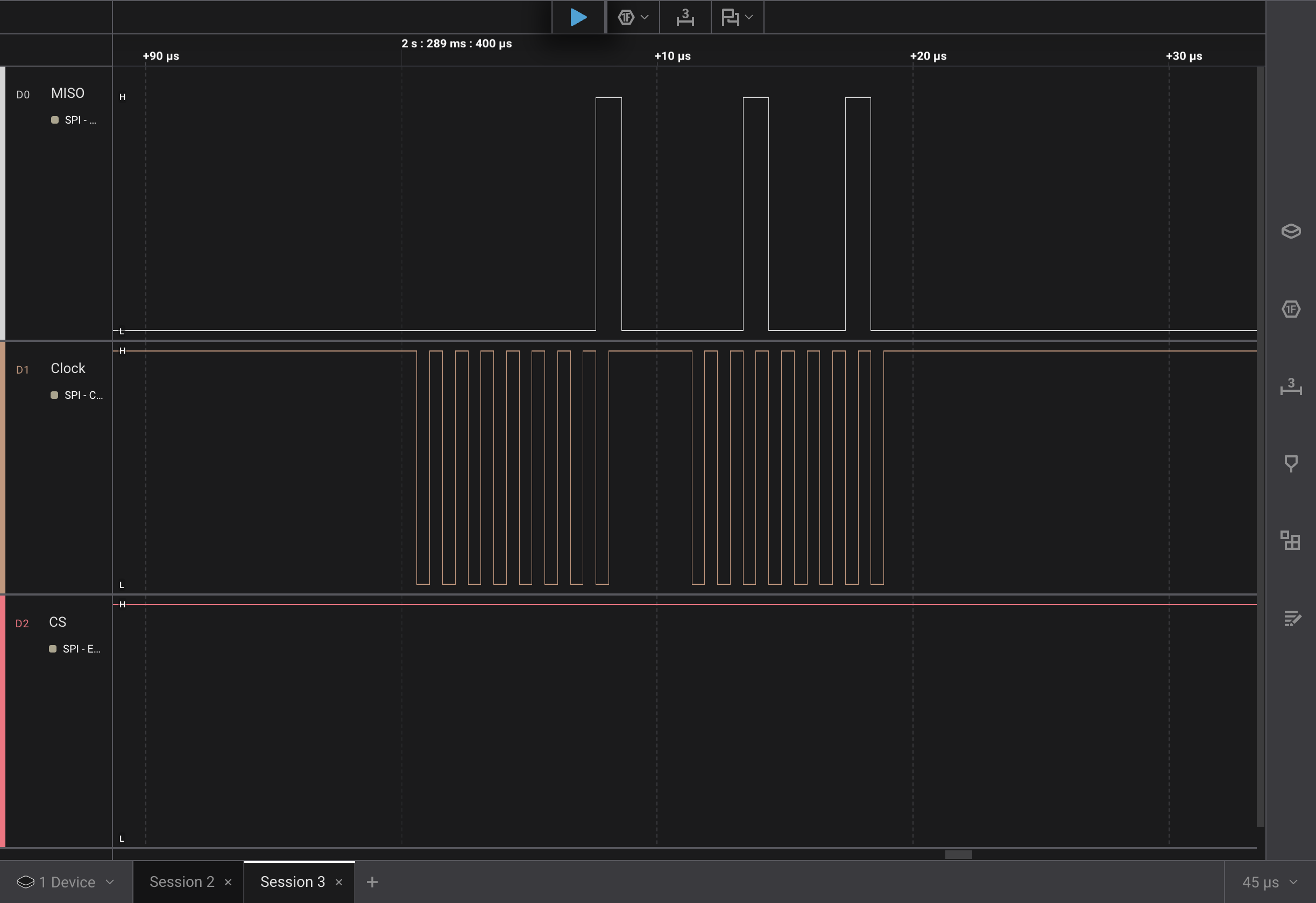
This looked much better!
As mentioned, I had used 1 initially to try and get the slowest speed, I was
thinking of trying to blink an led with the SPI signal. Clearly the 1 Hz was too
low to be valid. Since I’m using the logic analyzer anyway, there really isn’t a
need to visualize the messages with an LED blink.
Debugging Chip Select
There was still the problem with the CS not being activated.
Time to look at the Arduino SPI docs. Oh yah, those don’t exist…
Running across https://www.pjrc.com/teensy/td_libs_SPI.html#ss, the author mentions
The SPI library does not control the SS signals, because devices differ on when this is used, whether it is held low for multiple transfers or for each individual transfer, and so on. Control SS with digitalWrite().
In hindsight, this makes sense. In Serial Peripheral Interface on PMW3320DB-TYDU I mentioned how multiple peripherals could be on the same SPI clock and data lines. Each peripheral would know when to listen based on its chip select being activated. This means there may be more than one chip select line on the controller so the library might not know what the caller wants.
I also happened to re-look at the generic Arduino SPI docs which say:
With most SPI devices, after SPI.beginTransaction(), you will write the Chip Select pin LOW, call SPI.transfer() any number of times to transfer data, then write the CS pin HIGH, and finally call SPI.endTransaction().
(I think I’ve mentioned before, following instructions isn’t always my strong suite)
I must have been mislead by the SPI.begin() function taking an ss parameter.
I first tried to initialize it high, and then toggle it in the code before and after transferring the bytes.
Code setting chip select manually
#include <SPI.h>

void setup() {
  SPI.begin();
  digitalWrite(SS, HIGH);
}

void loop() {
  SPISettings settings = SPISettings(1000000, SPI_MSBFIRST, SPI_MODE3);
  SPI.beginTransaction(settings);
  digitalWrite(SS, LOW);
  SPI.transfer(0x01);
  SPI.transfer(0x22);
  digitalWrite(SS, HIGH);
  SPI.endTransaction();
  delay(1000);
}
This still didn’t work…
After a bit of head scratching, I realized that if begin() wasn’t setting up
the SS pin to be activated when sending bytes with SPI, it might not even be
configuring the pin.
I added a line to specify the pin as output in setup()
void setup() {
  SPI.begin();
  pinMode(SS, OUTPUT);
  digitalWrite(SS, HIGH);
}
Rerunning the capture I got:
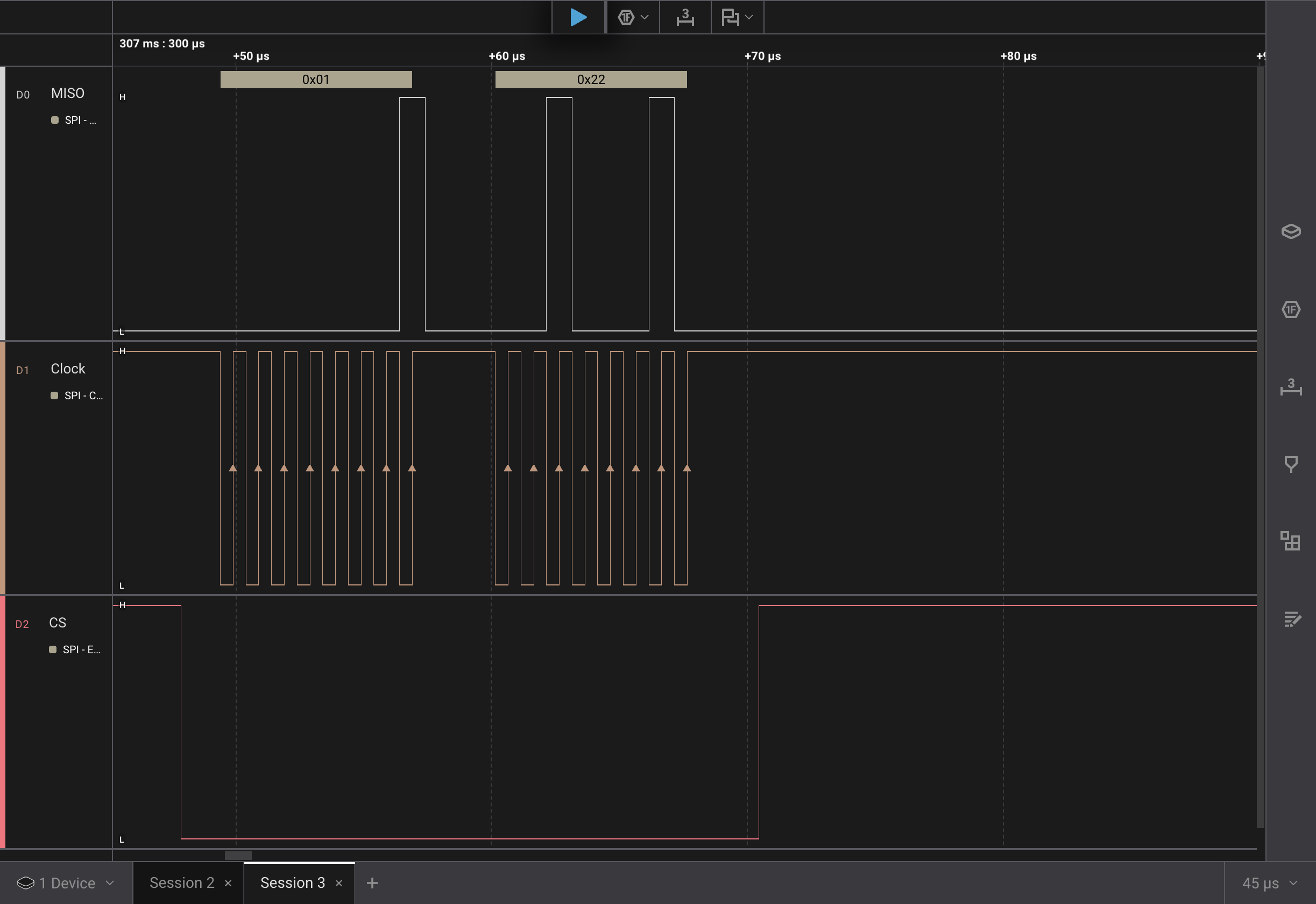
Success! The logic pro was able to correctly decode the 0x01 and 0x22
values.
It appeared that the ss parameter to the SPI.begin() function isn’t used at
all, at least for the esp32. I thought perhaps it’s used for another piece of
hardware that only allows one chip select.
Curiosity got the better of me and I decided to do some digging. I found the
implementation of begin() for the esp32 boards,
SPI.cpp.
The _ss is assigned, but is never actually used within the begin() function.
Looking further though SPI.cpp, I found
setHwCs().
This seems to use the _ss variable. Based on the name of the function it
seems like it might leave the activation of chip select up to the hardware
implementation of SPI.
I figured why not give it a try.
#include <SPI.h>

void setup() {
  SPI.begin();
  SPI.setHwCs(true);
}

void loop() {
  SPISettings settings = SPISettings(1000000, SPI_MSBFIRST, SPI_MODE3);
  SPI.beginTransaction(settings);
  SPI.transfer(0x01);
  SPI.transfer(0x22);
  SPI.endTransaction();
  delay(1000);
}

It works! The hardware chip select automatically activates for each byte. More
likely each transfer() call.
Thoughts and What’s Next
While I got the hardware chip select to function, I don’t think it will work with the PMW3320DB-TYDU, because it’s framing each byte and not each transaction. From the ADNS-3050 data sheet
If NCS is raised during a transaction, the entire transaction is aborted and the serial port will be reset.
One may notice that the data, MOSI, line idles low. The captures from
snooping on the
pmw3320DB-TYDU SPI
had the data line idling high. I don’t think the idle value matters. I think as
long as the line is in the correct state when the clock transitions either end
will read the value correctly.
I think the next steps will be to re-create the startup/reset cycle that the EX-G uses for the PMW3320DB-TYDU sensor. The first pass will not be connected to the PMW3320DB-TYDU sensor, instead the data will be captured re-using the bread board set up from above. Once that is ironed out and looks good then I’ll try connecting it to the PMW3320DB-TYDU sensor.