Seeed Studio XIAO esp32c6
The Atmega32U4 board I’ve been using for the Wired Trackball project is 5V. While the PMW3320DB-TYDU optical sensor in the EX-G trackball has an operating voltage of 2.1-3.4V, with an absolute max of 3.6V. To ensure I don’t let the magic smoke out of the PMW3320DB-TYDU I needed to find some way to use a lower voltage.
To continue to use the Atmega32U4 board I would need a voltage regulator for powering the PMW3320DB-TYDU and a level shifter for communicating with it over SPI. Many versions of these components can be found at online retailers like DigiKey. The individual components are often less than $1, but the retailers (understandably) charge shipping that’s $6-$8. This means I’ll likely pay ~$10 for the components. Once in hand I would need to wire the components up and place them and the board inside the EX-G.
Instead of doing this, I decided to revisit what I was going to use for the main controller. There are 3.3V versions of the Atmega32U4 board, but they’re a bit harder to find. Doing some internet searching, I stumbled on the Seeed Studio XIAO esp32c6. This board has a 3.3V power pin and can be had for ~$8 with shipping.
The esp32c6 board is about half the size of the Atmega32U4 board. The size of the Atmega32U4 was never an issue. The Atmega32U4 had 18 pins which could be used as digital inputs or outputs (I/O). While the esp32c6 has 11.
To keep the implementation simple, I will need at least 9 I/O pins to meet my initial project requirements.
| Function | I/O pins |
|---|---|
| Optical Sensor | 4 pins for SPI |
| Scroll Wheel | 2 pins for rotary encoder |
| Left Click | 1 pin |
| Right Click | 1 pin |
| Middle Click | 1 pin |
The PMW3320DB-TYDU is a 3 pin SPI peripheral, but the controllers still need to use 4 pins. More on that in a later post.
I will likely use one of the remaining pins to leverage the PMW3320DB-TYDU interrupt signal, taking the total used up to 10.
The esp32c6 will meet my needs, but won’t leave much room for further expansion. Being my first foray into something like this, I think it’s a reasonable trade off. My current mouse only supports what I have listed in my initial requirements. If I do want to expand functionality I would probably be revisiting other decisions as well.
Using the esp32c6 with Arduino IDE
First thing I did with the esp32c6 development board was solder on the pin headers. See Soldering Pin Headers to Atmega32U4 for how that’s done, taking into account my soldering skills have not improved.
With the pin headers on the esp32c6, I was ready to see about programming it with the Arduino IDE and getting it to blink. Technically I didn’t need to have the pin headers on for getting the board to blink. My goal was to get the board to blink similar to what I did to initially program the Atmega32u4.
The board isn’t supported by default in the Arduino IDE and some steps are necessary to get it working. There are instructions available on the manufacturer’s website, https://wiki.seeedstudio.com/xiao_esp32c6_getting_started/#software-preparation. Not being the best at following instructions and also not finding them initially, I more or less fumbled through the install and will provide the details.
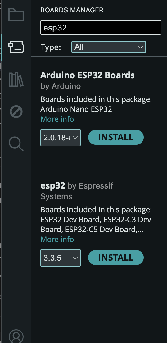
In the Arduino IDE go to Tools->Board->Boards Manager, search for and choose
the install for the esp32 By Espressif
The select board dropdown may show an unknown device or it may show “ESP32 Family Device”.
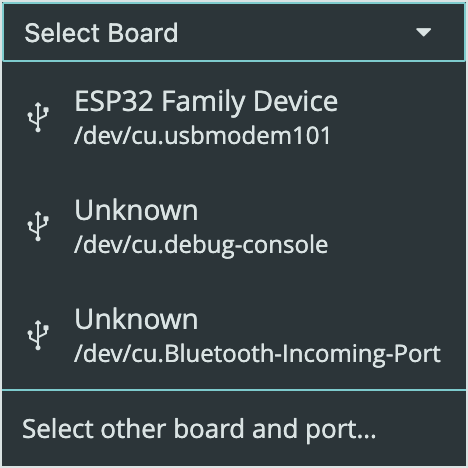
If either of these are shown they are not what you want. Instead click on the “Select other board and port” option to bring up the board selection dialog.
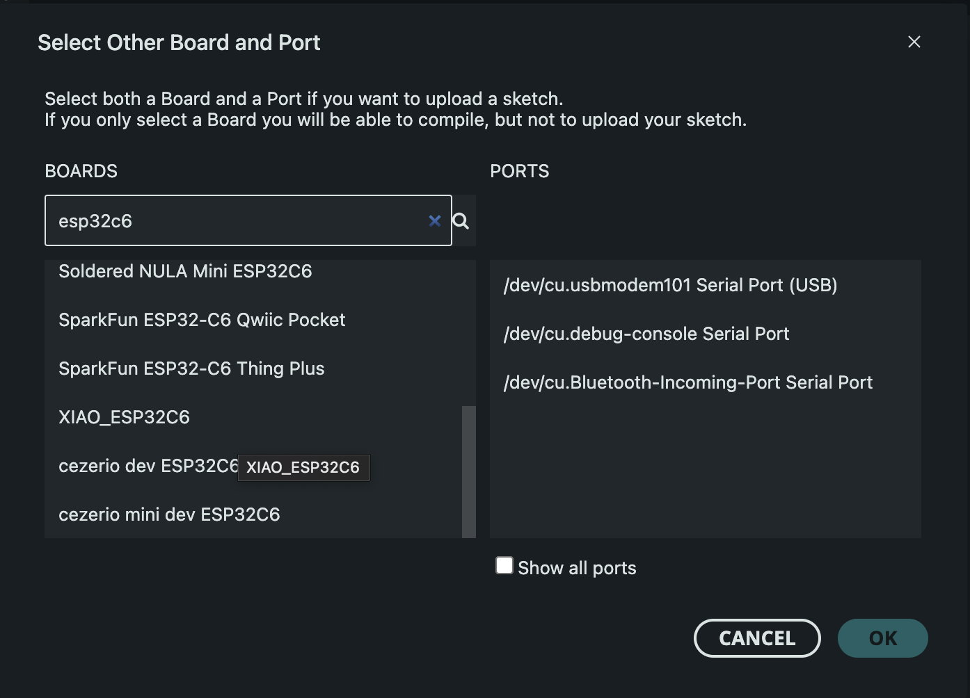
Searching for “esp32c6” will narrow down the results. The board to choose is the “XIAO_ESP32C6”. For me, the port was the same that showed up under the “ESP32 Family Device”, “usbmodem101 Serial Port”.
Similar to programming the Atmega32U4, I grabbed the
File->Examples->Basics->Blink sketch. Looking at the esp32c6 plugged in, it
seemed to already be blinking about once a second. To ensure that my upload was
what was running on the board I decided to modify the blink sketch to use 5
second blinks, by changing all the delays to use 5000.
delay(5000);
After this modification, I compiled and uploaded the sketch. The LED began to blink at a 5 second interval, success!!
Using the esp32c6 with Arduino CLI
Once the IDE was working I was sure I could get it working with the Arduino CLI.
Looking back at Developing Arduino Sketches with Neovim, I began with the esp32c6 plugged into my computer and seeing what the CLI showed when listing boards.
arduino-cli board list
This resulted in the following output:
Port                            Protocol Type              Board Name          FQBN                     Core
/dev/cu.Bluetooth-Incoming-Port serial   Serial Port       Unknown
/dev/cu.debug-console           serial   Serial Port       Unknown
/dev/cu.usbmodem101             serial   Serial Port (USB) ESP32 Family Device esp32:esp32:esp32_family esp32:esp32
I went to install the specified core with the CLI.
arduino-cli core install esp32:esp32
It turns out this wasn’t necessary, I’m guessing it must have re-used the install from the IDE.
I generated a test sketch like previously
arduino-cli sketch new test
cd test
echo 'void setup() {
    pinMode(LED_BUILTIN_RX, OUTPUT);
}

void loop() {
    digitalWrite(LED_BUILTIN_RX, HIGH);
    delay(1000);
    digitalWrite(LED_BUILTIN_RX, LOW);
    delay(1000);
}' > test.ino
I then went to compile this sketch using the FQBN provided from the above board list:
arduino-cli compile -u -p /dev/cu.usbmodem101 --fqbn esp32:esp32:esp32_family
This resulted in:
cp: /Users/nick/Library/Arduino15/packages/esp32/hardware/esp32/3.3.5/tools/partitions/{build.partitions}.csv: No such file or directory
This left me scratching my head. Doing some internet searching I ran across
avoid using the generic "ESP32 Family Device" board, which is a placeholder and does not work properly
Doing a search in /Users/nick/Library/Arduino15/packages/esp32/ for files with
the name esp32c6, I found one named XIAO_ESP32C6. So I tried updating my command:
arduino-cli compile -u -p /dev/cu.usbmodem101 --fqbn esp32:esp32:XIAO_ESP32C6
This gave me a compilation error:
/Users/nick/git/test/test.ino: In function 'void setup()':
/Users/nick/git/test/test.ino:2:13: error: 'LED_BUILTIN_RX' was not declared in this scope; did you mean 'LED_BUILTIN'?
    2 |     pinMode(LED_BUILTIN_RX, OUTPUT);
      |             ^~~~~~~~~~~~~~
      |             LED_BUILTIN
/Users/nick/git/test/test.ino: In function 'void loop()':
/Users/nick/git/test/test.ino:6:18: error: 'LED_BUILTIN_RX' was not declared in this scope; did you mean 'LED_BUILTIN'?
    6 |     digitalWrite(LED_BUILTIN_RX, HIGH);
      |                  ^~~~~~~~~~~~~~
      |                  LED_BUILTIN
The test sketch that I had reused was for the Atmega32U4 which uses a
LED_BUILTIN_RX. The esp32c6 does not have this, so I updated the sketch as
suggested in the error message to use LED_BUILTIN instead.
Everything compiled now, but the upload failed with
A fatal error occurred: Failed to connect to ESP32-C6: No serial data received.
For troubleshooting steps visit: https://docs.espressif.com/projects/esptool/en/latest/troubleshooting.html

Error during Upload: Failed uploading: uploading error: exit status 2
It took me a bit to figure this out. I tried jumping back to the IDE and re-uploading the example blink sketch and it got the same error.
The board was still running the 5 second blink upload from when I got the IDE working. That had the LED on for 5 seconds and then off for 5 seconds. This means the board would be inside the loop for 10 seconds at a time. I think the serial connection to upload the sketch was timing out during this 10 second loop. To work around this, I disconnected the board from my computer. Then right after I plugged the board back in, while it was still powering up, I ran the upload command again. This resulted in a successful upload.
ESP32 Family Device
An observant reader may notice that when I mentioned connecting the board with
the IDE, I said not to use the “ESP32 Family Device”, but then for the CLI
work I tried to use the esp32:esp32:esp32_family FQBN.
When I initially connected the esp32c6 board to the Arduino IDE, the board
showed up as “Unknown”. It’s only once I went to write this post and come back
to get some screenshots that the IDE started to recognize it as “ESP32 Family
Device”. So when I was doing the CLI exercise, I didn’t yet know about the
esp32_family issue.