Debugging 3-Wire SPI Controller
In the previous post, I tried and failed to get the esp32c6 to work as a three wire SPI controller. So in this post I’m hoping to figure out how to get it working correctly.
To try and get the four wire SPI of the esp32c6 to work with a three wire SPI, I connected a 10 kΩ resistor between the SPI output and input of the esp32. The idea being that when the esp32c6 is writing bytes out, even though it would be reading the same bytes in, it wouldn’t care what they are. My limited understanding, is the resistor serves to prevent a direct short between the output and input.
Doing some digging around I ran across a document from TI for calculating I2C pullup resistor sizes, I2C Bus Pullup Resistor Calculation.
Most of the document is above my limited understanding, but something that stood out to me:
If the pullup resistor value is too high, the I2C line may not rise to a logical high before it is pulled low.
This seems to imply that the pullup resistor can have an effect on how quickly the digital signal can be toggled. While I don’t think the 10 kΩ resistor is technically a pullup resistor, it likely has a similar effect.
I cannot stress enough, I’m more or less jumping to conclusions here based on my very limited understanding of circuits and a piece of info I stumbled on. The intent of this post is to follow the trail and run some experiments to see what happens.
My wife gave me a t-shirt that says:
The Scientific Method:
- F**k Around
- Find Out
and that’s what’s going to happen here.
I’ve currently fleshed out three steps to take on this debugging journey:
- Improve SPI capture
a. Re-initialize PMW3320DB-TYDU every second in the
loop()b. Capture bothCOPIandCIPO - Slow down the SPI clock
- Try smaller resistors
Note: I’m going to transition over to using the Arduino SPI terminology of
COPIandCIPO.
MISO==CIPOandMOSI==COPI.
The first step will make it easier to analyze the second and third steps. The
second and third steps may or may not be mutually exclusive. I’m hoping at least
one will provide insight into the hypothesis that the resistor between the
COPI and CIPO pins may be too large, or provide more evidence to dig into.
Improve SPI Capture
Coding up the SPI initialization of the PMW3320DB-TYDU in
Failing to Control the PMW3320DB-TYDU with SPI
was done optimistically. My thinking was the sensor would only need to be
initialized once. Now that the intent is to debug the SPI messages coming from
the esp32c6, I want to make it easier to take new recordings of the SPI
messages. This means I will revert back to what was done in
Using Arduino SPI library, where the
loop() repeatedly, outputs the SPI message(s) and then delays for one second.
Code to initialize PMW3320DB-TYDU with SPI, in loop
#include <SPI.h>

const int tWakeup = 55;
// This time was re-used from capture taken for OEM EX-G initializing
// PMW3320DB-TYDU
const int tPowerUpCs = 2;

// Time between commands, in µs
//
// Based on https://www.espruino.com/datasheets/ADNS5050.pdf
// worst case is tsww at 30 µs, which is time from last bit of first byte to
// last bit of second byte. At max speed of, 1,000,000 Hz 8 bits would take 8 µs
// leaving a pause of 22 µs.
//
// The data sheet also mentions
//
//    SCLK to NCS Inactive, tSCLK-NCS, 20 µs from last SCLK rising edge to NCS
//    (for write operation) rising edge, for valid SDIO data transfer.
//
// This seems to imply that we need 20 μs before moving chip select back high,
// so we'll cheat and re-use this value of 22 (for now?)
const int tWµs = 22;

const int IDLE_READ = 0xFF;

const int PROD_ID = 0x00;
const int POWER_UP_RESET = 0x3A;
const int PERFORMANCE = 0x22;
const int RESOLUTION = 0x0D;
const int AXIS_CONTROL = 0x1A;
const int BURST_READ_FIRST = 0x42;
const int MOTION = 0x02;
const int DELTA_X = 0x03;
const int DELTA_Y = 0x04;

typedef struct {
  bool moved;
  int x;
  int y;
} Movement;

SPISettings settings;

void setup() {
  SPI.begin();
  settings = SPISettings(1000000, SPI_MSBFIRST, SPI_MODE3);
  pinMode(SS, OUTPUT);
}

void loop() {
  initPmw();
  delay(1000);
}

void initPmw() {
  // Drive High and then low from https://media.digikey.com/pdf/data%20sheets/avago%20pdfs/adns-3050.pdf
  digitalWrite(SS, LOW);
  digitalWrite(SS, HIGH);
  delay(tPowerUpCs);
  digitalWrite(SS, LOW);
  delay(tPowerUpCs);

  delay(tWakeup);

  write(POWER_UP_RESET, 0x5A);
  read(PROD_ID);
  write(PERFORMANCE,0x80);
  write(0x1D,	0x0A);
  write(0x14,	0x40);
  write(0x18,	0x40);
  write(0x34,	0x28);
  write(0x64,	0x32);
  write(0x65,	0x32);
  write(0x66,	0x26);
  write(0x67,	0x26);
  write(0x21,	0x04);
  write(PERFORMANCE, 0x00);
  write(RESOLUTION,	0x86);
  read(AXIS_CONTROL);
  write(AXIS_CONTROL,	0xA0);
  write(BURST_READ_FIRST,	0x03);
  read(MOTION);
  read(DELTA_X);
  read(DELTA_Y);
}

Movement readMovement() {
  uint8_t motion = read(MOTION);
  Movement movement = {};
  if (motion) {
    movement.moved = true;
    movement.x = (int8_t)read(DELTA_X);
    movement.y = (int8_t)read(DELTA_Y);
  }
  return movement;
}

void write(uint8_t reg, uint8_t value) {
  digitalWrite(SS, LOW);
  SPI.beginTransaction(settings);
  SPI.transfer((uint8_t)(0x80 | reg));
  delayMicroseconds(tWµs);
  SPI.transfer(value);
  delayMicroseconds(tWµs);
  SPI.endTransaction();
  digitalWrite(SS, HIGH);
}

uint8_t read(uint8_t reg) {
  digitalWrite(SS, LOW);
  SPI.beginTransaction(settings);
  SPI.transfer(reg);
  delayMicroseconds(tWµs);
  uint8_t ret_value = SPI.transfer(IDLE_READ);
  delayMicroseconds(tWµs);
  SPI.endTransaction();
  digitalWrite(SS, HIGH);
  return ret_value;
}
The setup used in
Failing to Control the PMW3320DB-TYDU with SPI
initially captured the CIPO pin of the esp32c6. When the SPI messages seemed
incorrect, the capture was moved over to the COPI pin.
In order to get a better understanding of what’s going on, both the COPI and
CIPO pins will be captured concurrently. This will require modifying the
wiring between the esp32c6 and the logic analyzer.
The connections will be as follows:
| esp32c6 | Logic Analyzer | Function |
|---|---|---|
| D10 | Channel 0 | COPI |
| D9 | Channel 1 | CIPO |
| D8 | Channel 2 | Clock |
| D3 | Channel 3 | Chip Select |
How this might look on a bread board:

Previously, I had put the CIPO to a random channel and then hid it,
when configuring the SPI analyzer of
Saleae Logic Pro 2.
This time when configuring the SPI analyzer, the CIPO channel will be captured
and displayed with the other three channels.
Capturing Both COPI and CIPO
The first capture will include the 10 kΩ resistor between the COPI and CIPO
pins. The thought is, it should look similar to the first capture from
Failing to Control the PMW3320DB-TYDU with SPI.
If the capture is different, in particular if it has the correct SPI messages,
it may be an indicator that initializing the PMW3320DB-TYDU in the setup()
function is too soon in the esp32c6 startup process to reliably use SPI.
The capture:
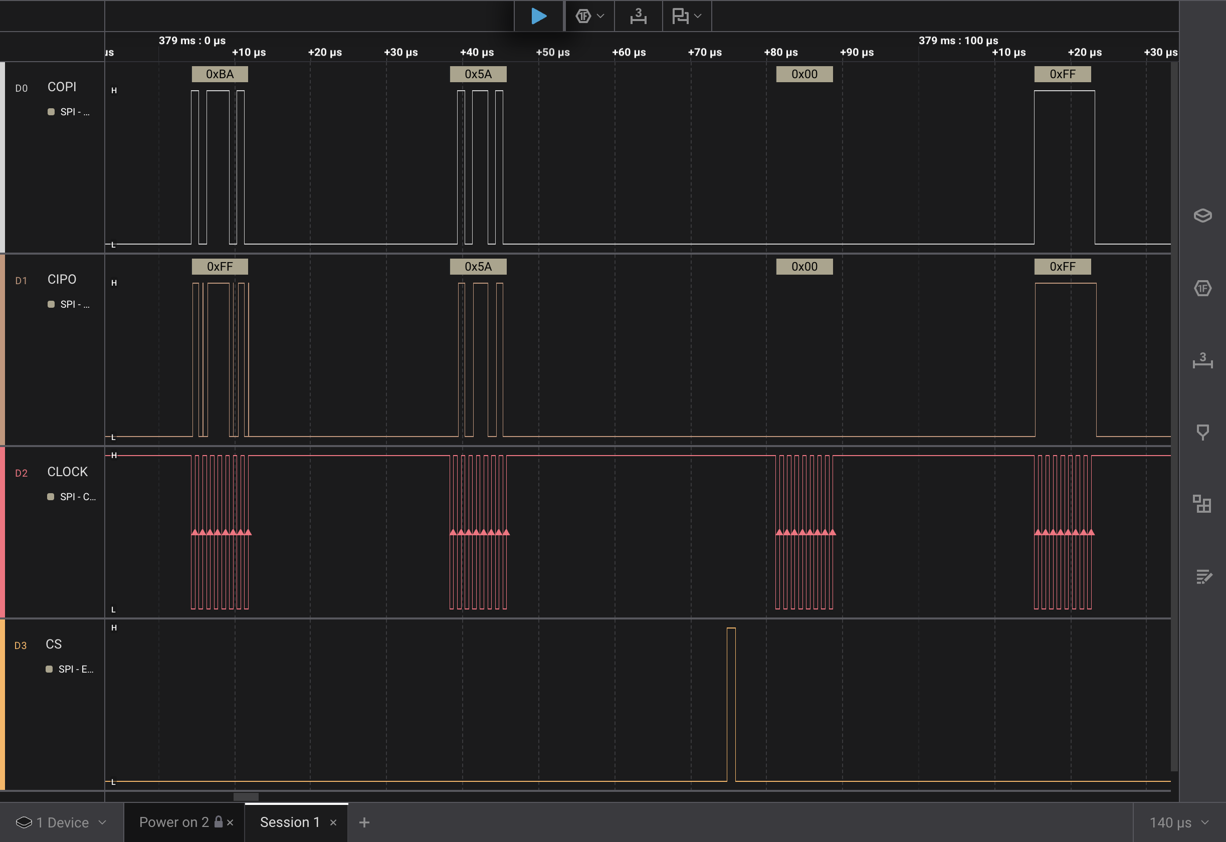
Right away we can see the first two bytes on the COPI channel are 0xBA and
0x5A. These represent the POWER_UP_RESET, which is expected. However the CIPO
capture is showing 0xFF and 0x5A. The first byte is incorrect, why?
It may be good to spend some time focusing on that first byte. Let’s zoom in on it:
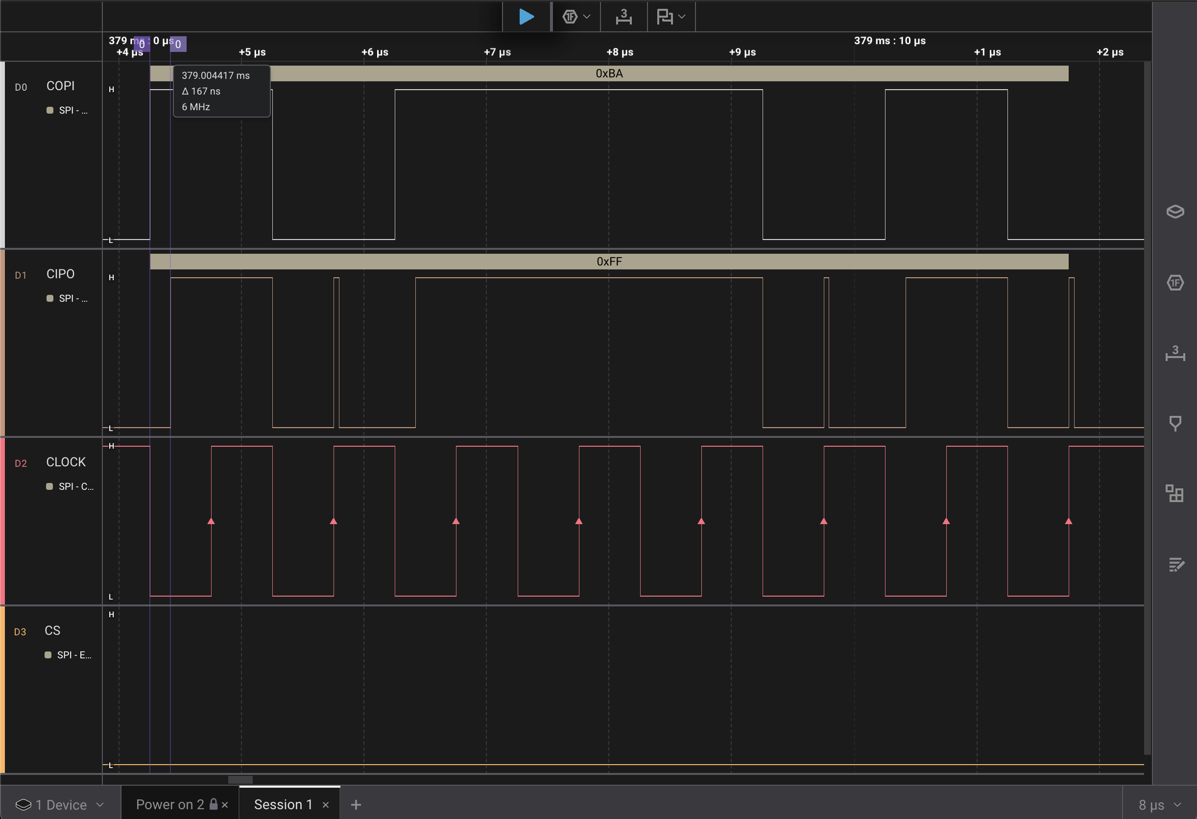
This is interesting. There are a number of, what look like, stray rises on the
CIPO channel. They correspond closely to the clock rises. Due to CPHA being
trailing edge, the CIPO rising when the clock rises means they’re interpreted
as high values.
I added some measurement bars, the purple lines to the left of the image. The
measurement starts with the first rise of the COPI channel and ends with the
first rise of the CIPO channel. We can see there is a delay of 167 ns. My
understanding is that time represents how long it takes for the signal to get
across the 10 kΩ resistor.
0xBA is 0b10111010. There are no consecutive zeros. I was thinking: if
there were consecutive zeros, maybe the COPI channel was going low, then
floating, and going back low. With the stray rise being a result of the COPI
channel floating.
The rises happen when the clock rises. Perhaps this is some kind of noise here.
If the resistor is too much, could it be that the clock pin being next to the
CIPO in hardware has more effect on the CIPO value than the COPI across
the resistor?
I may have latched on to the resistor hypothesis and am trying too hard to make it fit the cause of the behavior.
Slowing Down the SPI Clock
In the post on
using the Arduino SPI library,
I had attempted to use a clock frequency of 1 Hz. This failed to behave
correctly, so I jumped all the way up to a frequency of 1,000,000 Hz. There is
likely a slower frequency that the esp32c6 SPI could reasonably run at. The
slower frequency might give some more insight into the discrepancy between the
COPI and CIPO data lines.
My plan is to find the lowest frequency that the esp32c6 SPI will operate at. I found clk_tree_defs.h which as some frequency defines. It has a slow clock frequency define:
#define SOC_CLK_OSC_SLOW_FREQ_APPROX 32768 /*!< Approximate OSC_SLOW_CLK (external slow clock) frequency in Hz */
To my inexperienced electronics mind, 32 KHz seems a bit fast for the slow value. I’ll start by setting the SPI frequency to 32,768 Hz. Then halve or double depending on if it works. Continuing on that path until I find the frequency that stops working and the lowest one that works
| Frequency | Good Clock Signal in Capture |
|---|---|
| 32768 | No |
| 65536 | Yes |
32,768 didn’t work, but doubling to 65,536 did work. I made a table to track and it only got two entries…
Looking at the capture using 65,536 Hz:
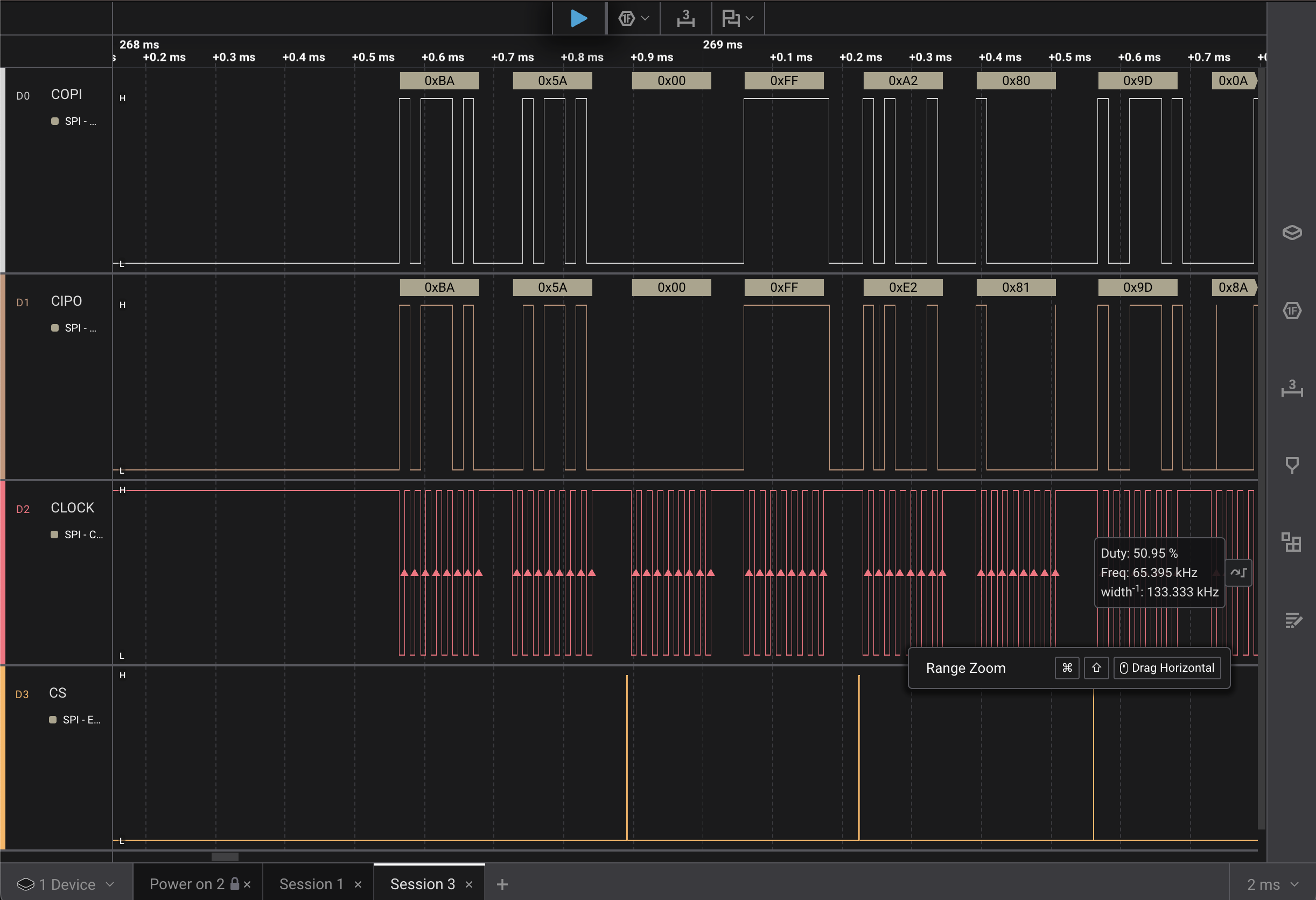
I wanted to call out that the Saleae Logic Pro 2 has a nice feature where if you hover over the clock signal, or any signal, it will provide a popup with the frequency. Looking to the right of the image it says 65.395 KHz which is pretty close to the 65,536 setting used.
Looking at the first SPI message byte pair, 0xBA and 0x5A. Both of those
values show up correctly on the COPI and CIPO channels. Looking at the third
SPI message pair, 0xA2 and 0X80, they’re showing up on the CIPO channel as
0xE2 and 0x81.
It seems that slowing down the clock signal did not alleviate the stray rises
showing up on the CIPO channel.
Changing Resistor Value
Looking at the above mentioned article from TI, I2C Bus Pullup Resistor Calculation, it provides an equation for the minimum pull-up resistor.
\[R_p(min) = \frac{V_{cc} - V_{ol}(max)}{I_{ol}}\]Looking at the esp32c6 data sheet it has \(I_{OL}\) at 23 mA. There are two voltage modes 1.8V and 3.3V. My setup is using the USB cable for power, so \(V_{cc}\) is 3.3. The data sheet says that \(V_{OL}\) is \(0.1 \times VDD\), where \(VDD\) is voltage from a power pin. My understanding is that puts \(V_{OL}\) more or less at a tenth of \(V_{cc}\) or 0.33.
Plugging the numbers in I get:
\[R_p(min) = \frac{3.3 - 0.33}{0.023} = 106.0714285714\]For the maximum size of a pull-up resistor the article has the following equation:
\[R_p(max) = \frac{t_r}{0.8473 \times C_b}\]\(t_r\) is the rise time of the signal. This is available in both the esp32c6 data sheet as well as the PMW3320DB-TYDU data sheet. \(C_b\) is the capacitive load of the line. I’m not sure what the captive load of the line is for my bread board setup and I’m not sure I’ll know what it will be of the final circuit I build.
With the minimum resistor size being 106 Ω and me not being quite sure what the maximum should be, I’m going to do the next best thing and guess. I will try a 1 kΩ resistor, because I have one handy. The important thing is to not go below the minimum, causing a short between the pins.
Swapping out the 10 kΩ for the 1 kΩ and doing a capture:
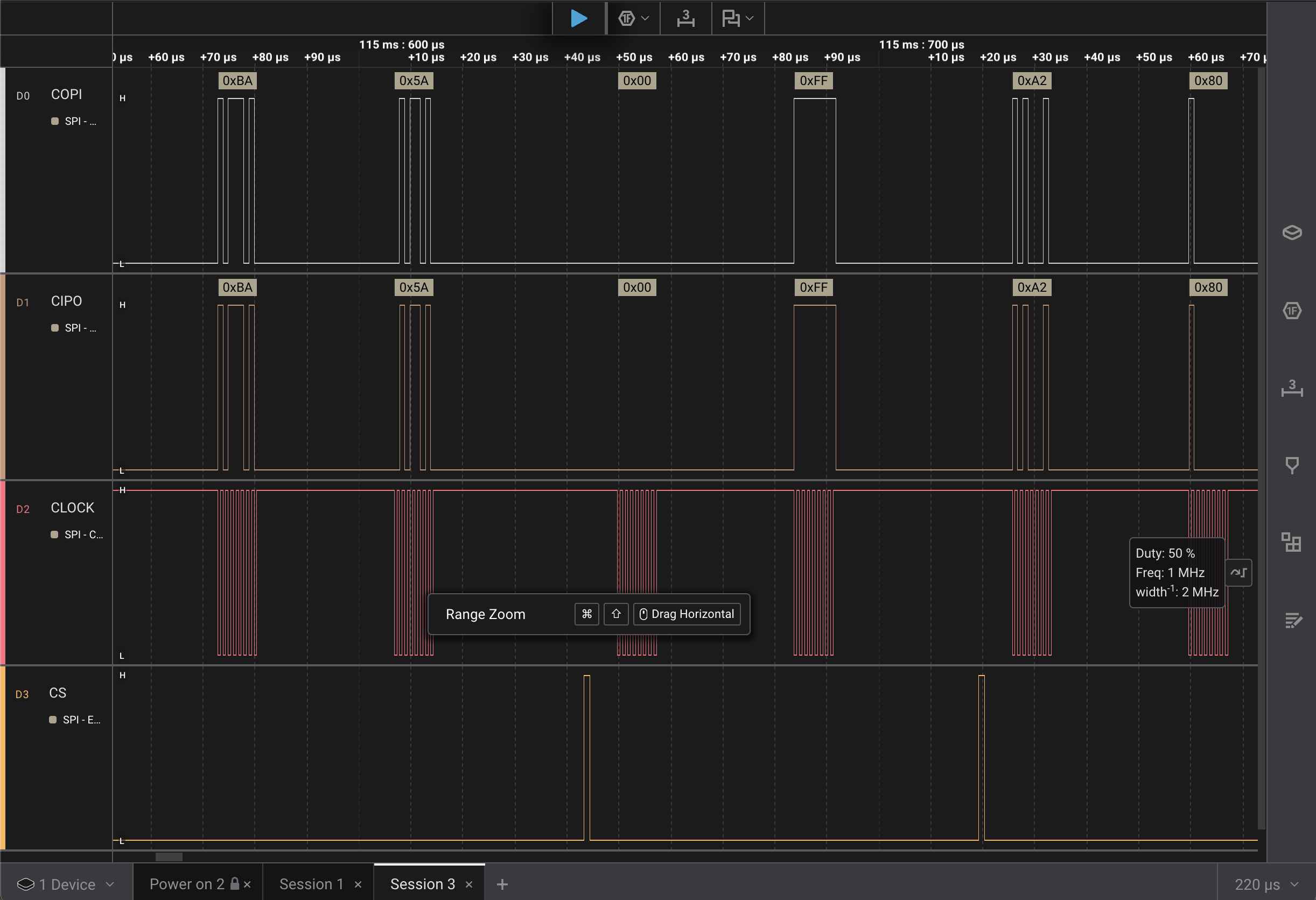
The image only shows the first three SPI message byte pairs. The COPI and
CIPO values are the same. I scrolled through all the message pairs and they
matched. The image also shows that I bumped the SPI frequency back to 1 MHz.
I’m a bit curious to see what the rise delay between the COPI and CIPO
channels is. Zooming in on the first rise:
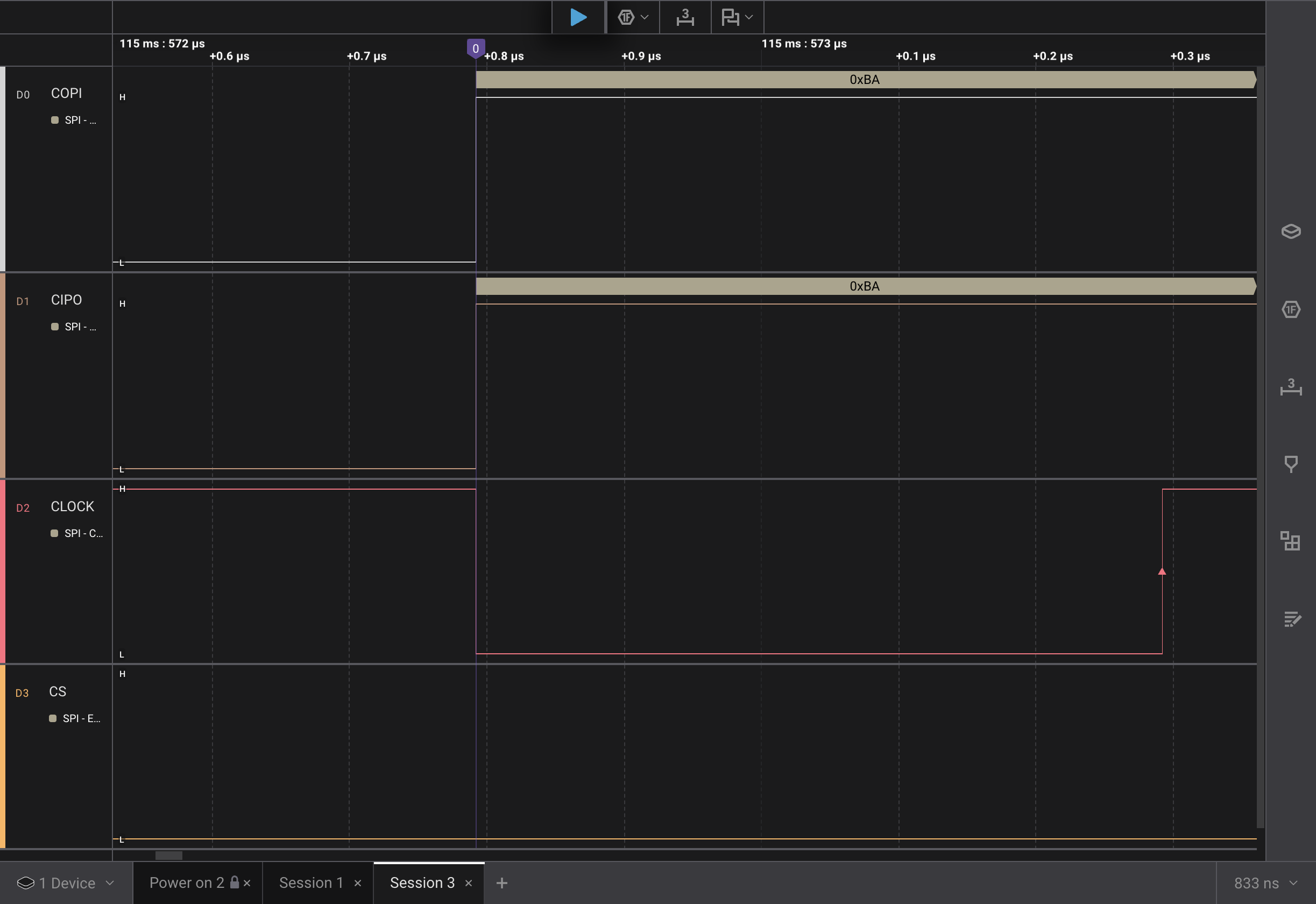
It looks like the COPI and CIPO channels are going up at the same time. More
likely, the delta can’t be measured within the precision of the logic analyzer I
have.
It looks like the 1 kΩ resistor solved the issue!
Looking back through this post as I edited and made corrections, I realize how lucky I got; stumbling on the TI article, latching on to the idea the resistor might be the problem, and then finding out the resistor was the problem. It doesn’t often happen this way where the first thing I consider happens to be the problem, especially in a domain where I lack quite a bit of knowledge. I wasn’t able to communicate my disappointment in the last post when the three wire SPI didn’t initially work. I think stepping away and letting the problem spin in my head overnight before coming back and trying to tackle it, likely contributed to the luck of zeroing in on it.