Failing to Control the PMW3320DB-TYDU with SPI
This post is going to focus on initializing the PMW3320DB-TYDU sensor using its SPI interface. The post will build off of a number of previous posts:
- Serial Peripheral Interface on PMW3320DB-TYDU
- Recording the traffic in the EX-G to PMW3320DB-TYDU
- Using Arduino SPI library
The Plan
The plan is to implement the
high speed power mode.
The previous capture of this mode showed that the EX-G was doing a full reset
when entering this mode. I’m hopeful that this will fully initialize the
PMW3320DB-TYDU to start sending the DELTA_X and DELTA_Y events. To keep this
first pass simple, it will be polling and not trying to utilize the interrupt
functionality available from the PMW3320DB-TYDU.
Initial execution of the SPI code will be done similar to the work in Using Arduino SPI library. Only the esp32c6 dev board and logic analyzer will be connected. The logic analyzer will be used to ensure the SPI messages are correct.
Once I have confidence the code is sending the correct SPI messages, then the PMW3320DB-TYDU will be connected to the esp32c6 SPI pins. The logic analyzer will be left in place to be able to read the messages to and from the two components.
The goal is to get the PMW3320DB-TYDU initialized and able to read trackball movements from it.
Revisiting 3-Wire SPI
When I initially discussed 3-wire SPI. I used a diagram where both the controller and peripheral only had one data line.

With the data line being used for both input and output. The esp32c6
hardware diagram
shows a MOSI (Master Out/Slave In) pin and a MISO(Master In/Slave Out) pin.
This is a four wire controller. The esp32c6 sends data out on the MOSI pin and
reads data in on the MISO pin. The PMW3320DB-TYDU only has the three wires
dedicated for SPI.
To get the esp32c6 to work with a three wire SPI peripheral a 10 kΩ will be
placed between the MOSI and MISO pins. The MISO pin will be the pin that
connects to the SDIO pin of the PMW3320DB-TYDU. Connecting the MISO and
MOSI pins is mentioned in a note on the Wikipedia article on
SPI.
It’s also mentioned in an
article
from TotalPhase, a manufacturer of SPI analyzers.

Wiring up in the bread board is very similar to the set up used in
Using Arduino SPI library, with
the exception that channel 0 of the logic analyzer is now connected to D9 of
the esp32c6 and there is a 10 kΩ resistor between D10 and D9.

Reading Bytes
One thing I glossed over in Using Arduino SPI library is how to read bytes with the library.
The SPI.transfer() function will send a byte out, while concurrently reading a
byte in. The function returns the read byte.
uint8_t valueIn = SPI.transfer(valueOut);
The Arduino SPI library goes into this behavior a bit.
The reason for this is that the act of writing to the outbound register is what causes the clock to start cycling. If you don’t provide any data to write, even if it’s all zeros or ones, means you would never initiate the clock. I typically create an 8 bit constant called “JUNK” with a value of 0xFF that I use for this purpose any time I want to make it clear that I am expecting the chip to ignore the outgoing value.
The author suggests a JUNK sentinel value of 0xFF. I don’t think this value
will work with the three wire setup. The MOSI and MISO lines are connected
to each other. If the MOSI line was sending out 0xFF, then it would pull the
normally low idle line high. I think the sentinel value needs to match the idle
value so that the MOSI line isn’t doing anything different and doesn’t pollute
the data coming back from the PMW3320DB-TYDU.
Coding the SPI Routine
The plan for the code is to have the setup() function initialize the SPI pins
and initialize the PMW3320DB-TDYU. Then in the loop() it will poll the
PMW3320DB-TDYU for motion. If motion is seen then it will make a Mouse.move()
call with the values.
Initial code attempt
#include <Mouse.h>
#include <SPI.h>

const int tWakeup = 55;
// This time was re-used from capture taken for OEM EX-G initializing
// PMW3320DB-TYDU
const int tPowerUpCs = 2;

// Time between commands, in µs
//
// Based on https://www.espruino.com/datasheets/ADNS5050.pdf
// worst case is tsww at 30 µs, which is time from last bit of first byte to
// last bit of second byte. At max speed of, 1,000,000 Hz 8 bits would take 8 µs
// leaving a pause of 22 µs.
//
// The data sheet also mentions
//
//    SCLK to NCS Inactive, tSCLK-NCS, 20 µs from last SCLK rising edge to NCS
//    (for write operation) rising edge, for valid SDIO data transfer.
//
// This seems to imply that we need 20 μs before moving chip select back high,
// so we'll cheat and re-use this value of 22 (for now?)
const int tWµs = 22;

const int IDLE_READ = 0x00;

const int PROD_ID = 0x00;
const int POWER_UP_RESET = 0x3A;
const int PERFORMANCE = 0x22;
const int RESOLUTION = 0x0D;
const int AXIS_CONTROL = 0x1A;
const int BURST_READ_FIRST = 0x42;
const int MOTION = 0x02;
const int DELTA_X = 0x03;
const int DELTA_Y = 0x04;

typedef struct {
  bool moved;
  int x;
  int y;
} Movement;

SPISettings settings;

void setup() {
  SPI.begin();
  settings = SPISettings(1000000, SPI_MSBFIRST, SPI_MODE3);
  pinMode(SS, OUTPUT);
  initPmw();
}

void loop() {
  Movement movement = readMovement();
  if (movement.moved) {
    Mouse.move(movement.x, movement.y);
  }
}

void initPmw() {
  // Drive High and then low from https://media.digikey.com/pdf/data%20sheets/avago%20pdfs/adns-3050.pdf
  digitalWrite(SS, LOW);
  digitalWrite(SS, HIGH);
  delay(tPowerUpCs);
  digitalWrite(SS, LOW);
  delay(tPowerUpCs);

  delay(tWakeup);

  write(POWER_UP_RESET, 0x5A);
  read(PROD_ID);
  write(PERFORMANCE,0x80);
  write(0x1D,	0x0A);
  write(0x14,	0x40);
  write(0x18,	0x40);
  write(0x34,	0x28);
  write(0x64,	0x32);
  write(0x65,	0x32);
  write(0x66,	0x26);
  write(0x67,	0x26);
  write(0x21,	0x04);
  write(PERFORMANCE, 0x00);
  write(RESOLUTION,	0x86);
  read(AXIS_CONTROL);
  write(AXIS_CONTROL,	0xA0);
  write(BURST_READ_FIRST,	0x03);
  read(MOTION);
  read(DELTA_X);
  read(DELTA_Y);
}

Movement readMovement() {
  uint8_t motion = read(MOTION);
  Movement movement = {};
  if (motion) {
    movement.moved = true;
    movement.x = (int8_t)read(DELTA_X);
    movement.y = (int8_t)read(DELTA_Y);
  }
  return movement;
}

void write(uint8_t reg, uint8_t value) {
  digitalWrite(SS, LOW);
  SPI.beginTransaction(settings);
  SPI.transfer((uint8_t)(0x80 | reg));
  delayMicroseconds(tWµs);
  SPI.transfer(value);
  delayMicroseconds(tWµs);
  SPI.endTransaction();
  digitalWrite(SS, HIGH);
}

uint8_t read(uint8_t reg) {
  digitalWrite(SS, LOW);
  SPI.beginTransaction(settings);
  SPI.transfer(reg);
  delayMicroseconds(tWµs);
  uint8_t ret_value = SPI.transfer(IDLE_READ);
  delayMicroseconds(tWµs);
  SPI.endTransaction();
  digitalWrite(SS, HIGH);
  return ret_value;
}
This is a bit of code, so it’s collapsed by default.
The initPmw() performs the
high speed power mode.
The readMovement() function will read from the movement registers. It is not
reading in burst mode and instead is reading one register at a time.
There are two helper functions for reading and writing registers. These functions wrap up the logic of toggling the chip select before putting bytes on the SPI data line.
One thing to note about the behavior of these functions, is there is a delay
after every SPI.transfer() call. When
recording the traffic between the EX-G to PMW3320DB-TYDU the captures showed about a ~24
µs delay between each byte written to the SPI bus. There was also ~ a 17 µs
delay between the last bit written and the chip select going inactive. These
could have been chalked up to processing delays. However, looking through the
ADNS-5050 data sheet there
are some timing values; tSWW, tSWR, and tSCLK-NCS. These values mention the
required time delays before reading or writing subsequent bytes, and before
allowing the chip select to go inactive. It’s likely the delays in the capture
are the logic implemented to meet these delay requirements.
Considering the fastest the SPI can run is at 1 MHz, the fastest 8 bits could be transmitted is 8 µs. Taking the worst case, tSWW, of 30 µs and subtracting the 8 µs from that value, leaves 22 µs. The code uses 22 µs of delay always, this should ensure that any write and read operation is correct regardless of what operation happened before it. There may be some room for performance improvement here, but I’ve got a hunch I won’t notice anything.
Testing out the code
First thing is to compile the code.
arduino-cli compile -u -p /dev/cu.usbmodem1301 --fqbn esp32:esp32:XIAO_ESP32C6
This resulted in:
In file included from /Users/nick/git/pmw/pmw.ino:1:
/Users/nick/Documents/Arduino/libraries/Mouse/src/Mouse.h:25:10: fatal error: HID.h: No such file or directory
   25 | #include "HID.h"
      |          ^~~~~~~
compilation terminated.
Doing some internet searching I find that the esp32c6 does not support USB HID (mouse) emulation. The newer esp32s3 does. I looked at the s3 data sheet and thought, “I don’t need those features”. I didn’t think, or really know, to look what the USB interface supported.
So I’ll remove the mouse logic from my code and some serial print statements and focus on snooping with the logic analyzer.
  if (movement.moved) {
    Serial.print("Delta x: ");
    Serial.println(movement.x);
    Serial.print("Delta y: ");
    Serial.println(movement.y);
  }
The code compiles and uploads now.
Since the setup() function does most of the work, I’m going to set the
Saleae Logic Pro 2 software to trigger when CS goes low, like was done in
Recording the traffic in the EX-G to PMW3320DB-TYDU.
Then I’m going to power on the esp32c6 and hope that it doesn’t happen to
trigger until the setup() function is executed.
The output was not what I expected:
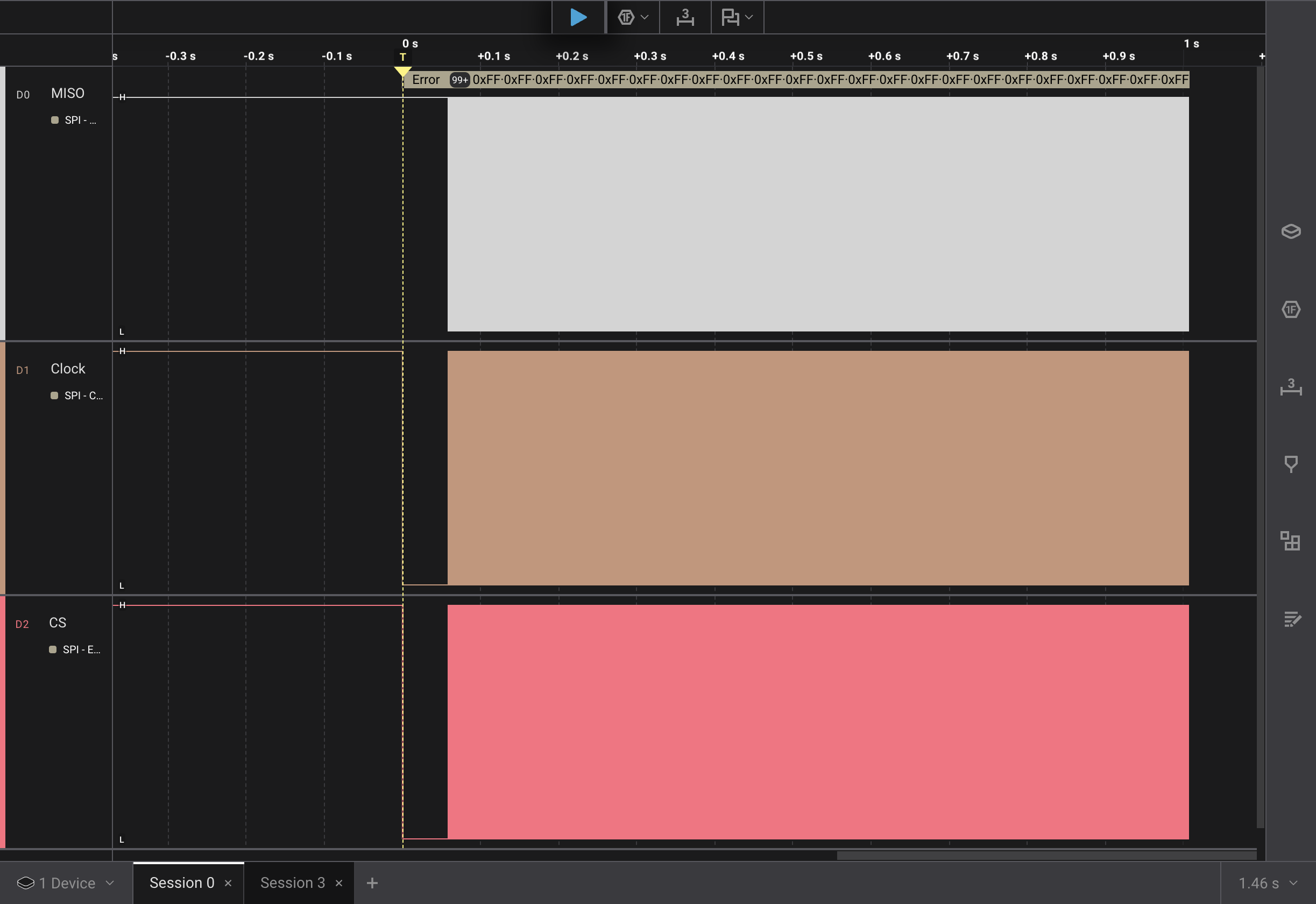
A couple of things to note:
- after the trigger event, it’s more or less solid messages
- The data line now looks to be idling high
Thinking about the solid messages for a bit, I realized the loop() is always
trying to read mouse movements. This is a constant stream of messages to get the
movement values. So I decide to get rid of that and empty the loop()
function body.
With the data line looking like it’s idling high, I decide to change the
IDLE_READ value to 0xFF instead of 0x00.
Time to rerun the test.
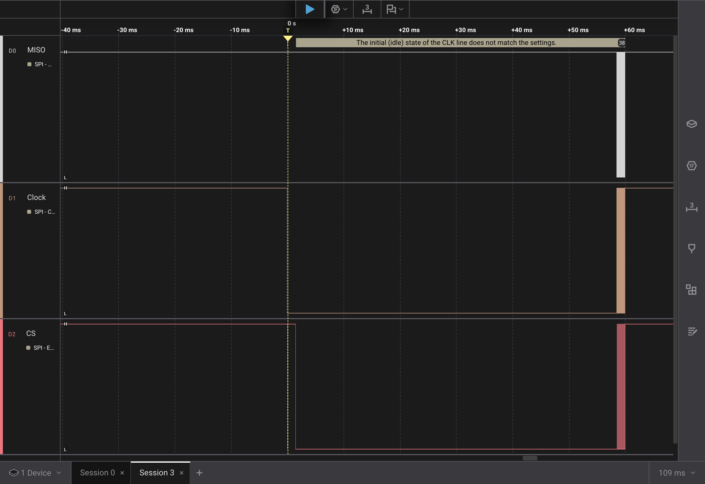
This is looking better. Zoomed out, it seems to match the capture from Recording the traffic in the EX-G to PMW3320DB-TYDU.
CSinitially goes lowCSgoes high for ~1.4 msCSgoes back low for 57 ms- the initialization messages are sent
Zooming in on the data:
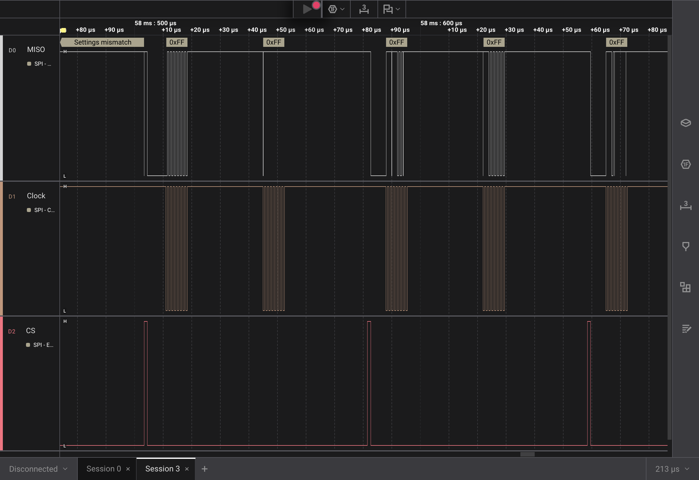 The Pro Logic 2 is failing to properly decode the SPI messages. The data line
(top row) also seems to go low before the chip select goes active.
The Pro Logic 2 is failing to properly decode the SPI messages. The data line
(top row) also seems to go low before the chip select goes active.
I decide to remove the 10 kΩ resistor between the MOSI and MISO pins. Moving
the logic analyzer capture to the MOSI line. The intent is to understand if
the three pin SPI setup I have is interfering, or if initializing the
PMW3320DB-TYDU in the setup() function might be too soon and the
initialization needs to be a one time event in the loop().
Rerunning the test and zooming in on some messages I see:
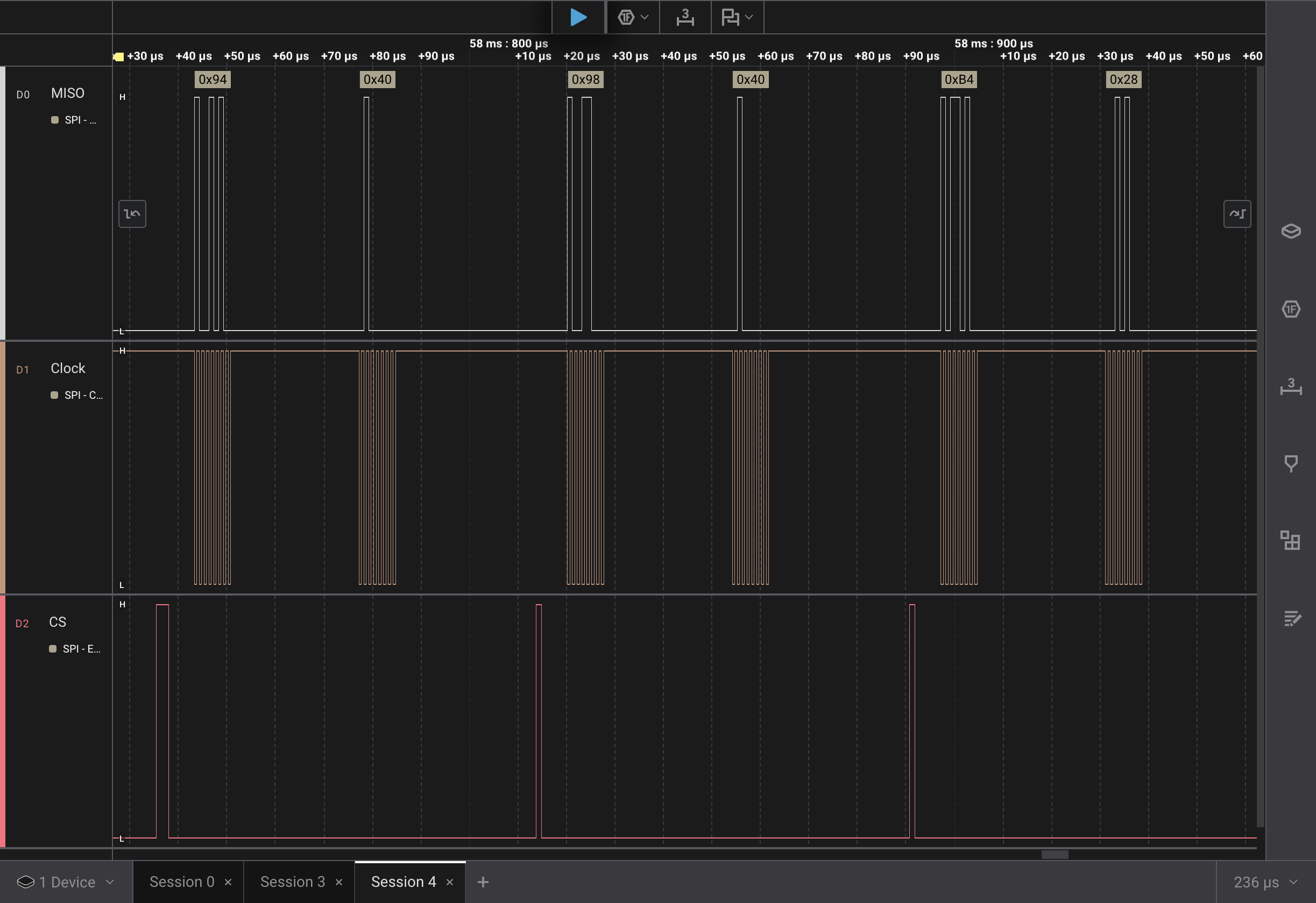
Those decoded values seem correct and match the fourth, fifth and sixth rows of the power on sequence.
| Command | Register | Value |
|---|---|---|
| Read | 0x00 PROD_ID | 0x3B |
| Write | 0x22 PERFORMANCE | 0x80 |
| Write | 0x1D UNKNOWN | 0x0A |
| Write | 0x14 UNKNOWN | 0x40 |
| Write | 0x18 UNKNOWN | 0x40 |
| Write | 0x34 UNKNOWN | 0x28 |
Conclusion
I’ve got two problems to solve in order to move forward:
- The 10 kΩ resistor between the
MOSIandMISOlines isn’t working for talking to a three pin SPI. - The esp32c6 doesn’t support acting as a USB mouse.
I’ll need to look into the three pin SPI some more. I’m sure there is a solution, I likely just need to get a better understanding.
For the USB mouse, I’m not sure what I want to do there. I think I need to get the three pin SPI working before I try to make any decisions on how to move forward.