Using EX-G hardware switches
One thing I’ve been pondering since starting this adventure of converting a wireless trackball to wired, is how to connect the EX-G hardware switches to the ESP32-C6 (or similar) board.
As discovered when disassembling the EX-G trackball, the EX-G switches (left, middle and right click) are part of the primary circuit board. This means the circuit board makes up the mechanical structure for engaging the switches.
My initial, naive, hope was that the switches would be integrated into the trackball case and wired to the circuit board. This would allow me to remove the wires going to the circuit board and connect them to the new controller.
With the circuit board being integral to the function of the switches I was
contemplating trying to wire all connections from the new controller directly to
the circuit board. This made me wonder if there might be a problem applying a
3.3 V power to the circuit board’s VCC.
The EX-G runs at ~2.2 V, even though it’s powered by a single AA battery that provides 1 V - 1.5 V. This indicates that there is a step up converter in the mix. I have no idea what applying a 3.3 V power to the output of the step up converter would do. While I’m not worried about preserving the EX-G circuit board, I don’t want to do something that results in unnecessary parasitic power loss, or creates a fire hazard.
In thinking about directly connecting to the circuit board more, I realized the PMW3320DB-TYDU optical sensor is the only component that needs power. It connects to the primary circuit board using a ribbon cable that can easily be disconnected. This means I can isolate the PMW3320DB-TYDU from the primary circuit board and wire it directly to the new controller.
The switches and scroll wheel are just signal lines: they short the microcontorller input to ground when activated. Power draw should be fairly small. Due to the low power usage, it may be feasible to wire the new controller directly to the switches, while they’re still on the board.
The switches attach to the circuit board with through holes. Their posts stick out the bottom of the board leaving enough surface area to solder wires to. These wires can then be connected back to the controller.
I was going to say “easily solder wires”, but looking back at my soldering skills, easily probably isn’t the correct adverb.
I think there’s a good chance I can reuse the ground on the circuit board by connecting it to the ground of the controller.
Switches On the Circuit Board
Taking a closer look at the switches on the EX-G circuit board, traces can be seen connecting the switches to the microcontroller. The left image is an unmodified close up. The right image has a blue highlight over the trace from the right click switch to the microcontroller and a magenta highlight over the trace from the left scroll switch to the microcontroller.
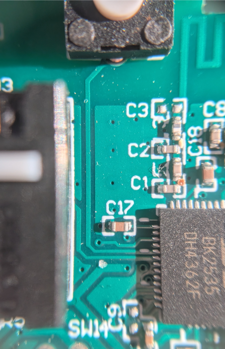
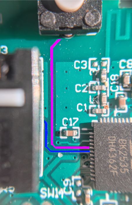
Since this is a left-handed trackball, what’s traditionally called the right-click is on the left side.
The switches connect directly to the pre-existing microcontroller. This means wiring the new controller directly to the switches may interact with the powered off microcontroller.
My initial thoughts on what might happen:
- The microcontroller will have no effect being included in the circuit
- The microcontroller provides a fake ground signal, making the switch always appear pressed.
- The microcontroller may allow the signal power to pass through partially
energizing the
VCCof the circuit board.
My hope is there is no effect. If it comes down to it I could cut or scrape through the traces to the microcontroller isolating the switches, while leaving the circuit board intact for the mechanical support of the switches.
The Plan
Connect one of the switches as an input to the ESP32-C6, using test connectors. Connect the ground from the ESP32-C6 to the common ground on the EX-G circuit board.
Determine if:
- The switch, while still connected to the circuit board, will function correctly as an input to the ESP32-C6.
- The idle high from the ESP32-C6 leaks through to the circuit boards
VCC.
The Circuit
The circuit for using the right click switch from the EX-G will be very similar to the one in the post “Using Internal Pull-up Resistor of the Atmega”. The main difference being that the switch will not be on the breadboard, instead the switch will remain on the EX-G circuit board.
Sample breadboard pictorial:

The ground in the diagram above will be the common ground of the EX-G circuit board. The connection will be from the ESP32-C6 to the negative battery terminal spring.
The Code
The code will be similar to that used in “Using Internal Pull-up Resistor of the Atmega”. Since the ESP32-C6 doesn’t support USB mouse, the code will instead use serial print statements.
bool clicked = false;
int buttonPin = 22;
void setup() {
  Serial.begin(115200);
  pinMode(buttonPin, INPUT_PULLUP);
}

void loop() {
  bool low = digitalRead(buttonPin) == LOW;
  if (low && !clicked)
  {
    clicked = true;
    Serial.println("Button pressed");
  }
  else if (!low && clicked)
  {
    clicked = false;
    Serial.println("Button released");
  }
}
The Test
Compile and upload the code, connect everything up, and then use the Arduino CLI
monitor subcommand to view the serial output.
I’m greeted with a stream of
Button pressed
Button released
Button pressed
Button released
Button pressed
This does not bode well…
Since the screen filled up, it’s hard to see when new messages are coming in and if they’ve stopped. One way to help out here is to add a value that changes on each print. Adding a counter to be printed with the messages should work.
Code with counter
int counter = 0;
bool clicked = false;
int buttonPin = 22;
void setup() {
  Serial.begin(115200);
  pinMode(buttonPin, INPUT_PULLUP);
}

void loop() {
  bool low = digitalRead(buttonPin) == LOW;
  if (low && !clicked)
  {
    clicked = true;
    counter++;
    Serial.println("Button pressed");
    Serial.println(counter);
  }
  else if (!low && clicked)
  {
    clicked = false;
    counter++;
    Serial.println("Button released");
    Serial.println(counter);
  }
}
With the counter in place, it shows that values don’t continually stream. They
increase a lot when initially making the last connection between the ESP32-C6 and
the switch.
Button pressed
215
Button released
216
Button pressed
217
Button released
218
Button pressed
219
It might be worth checking the VCC on the circuit board and see if power is
leaking back through the circuit board’s microcontroller. With the circuit
board disconnected from the ESP32-C6 the multimeter is showing 0.3 V.
There’s no power to the board, how does it have voltage?
I bet the board has some capacitors keeping a bit of a charge. It’s just a little bit, I wonder if shorting to ground through a wire is enough to drain it without any adverse effects. It’s worth a try.
After shorting VCC to ground, the multi meter is now reading 0.0 V. Nice!
Now I’m going to re-connect the ESP32-C6 and see what voltage is seen at the
EX-G circuit board VCC. With everything connected, the multimeter shows 0.7 V
at the VCC terminal. It seems that voltage from the input pin is leaking
through the EX-G microcontroller.
Just to make sure, I should probably check the input pin voltage. When everything is connected the pin voltage is 1.13 V. Disconnecting the pin from the right mouse click switch gives 3.19 V. The voltage isn’t being completely diverted to ground, but it’s enough to register as low.
I wonder what the resistance is between the right mouse click switch and VCC
is. Checking that with a multimeter results in 6.8 kΩ. Less than the commonly
suggested pull-up or pull-down resistor.
Conclusion
It’s looking like connecting the switches from the EX-G circuit board as is, is a no go. I’ll likely either need to cut the traces on the circuit board, or try to remove the microcontroller from the circuit board.