Assembling EX-G with ESP32S3
The time has finally come to put the EX-G back together. The code was completed in the following posts:
The only thing left is physically wiring the ESP32S3 to the EX-G hardware. To accomplish this I’m going to solder wires directly to the PMW3320DB-TYDU optical sensor and the underside of the EX-G’s circuit board.
Connection Mapping
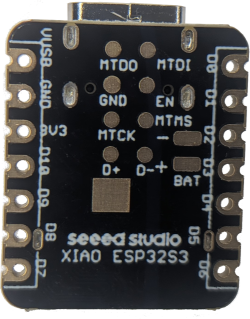
The ESP32S3 board has a total of 15 GPIO pins available. Along the sides there
are D0-D10. On the bottom there are four points MTDO, MTDI, MTCK, and
MTMS.
I decided that I would wire up as much as I can, even if I don’t use all of the connections right now.
| EX-G Function | GPIO PIN | Wire Color |
|---|---|---|
| Scroll Wheel | D0 | green |
| Scroll Wheel | D1 | yellow |
| Left Click | D2 | blue |
| Right Click | D3 | white |
| Middle Click | D4 | red |
| Scroll Left | D5 | green |
| Scroll Right | D6 | yellow |
| SPI Chip Select | D7 | white |
| SPI Clock | D8 | yellow |
| SPI CIPO | D9 | blue |
| SPI COPI | D10 | 1 kΩ resistor |
| Navigate Forward | MTDO | blue |
| Navigate Backward | MTDI | white |
| Ring Finger Click | MTCK | green |
| DPI Switch | MTMS | black |
| circuit board ground | GND | black |
| PMW3320DB-TYDU VDD | 3V3 | red |
This connects all of the potential EX-G inputs up.
The COPI pin will have a 1 kΩ resistor connected directly to the CIPO pin of the ESP32S3. The need for the resistor and its value was covered in Failing to Control the PMW3320DB-TYDU with SPI and Debugging 3-Wire SPI Controller.
Soldering the Connections
I’ll push wires into the holes along the side of the ESP32S3 and solder them in place there. The connections on the back of the ESP32S3 will require me to lay the wire ends on the pads and solder them flat.
I only have a through hole resistor. The D9 and D10 pins are closer together than the resistor body. A surface mount resistor might have been nicer, but I’ll make do. My plan is to pull the resistor through as much as possible and then cover it with heat shrink to try and prevent the terminals from coming into contact with anything.
I plan on re-using the solder that’s already on the through hole pins of the EX-G circuit board and PMW3320DB-TYDU sensor. I’ll likely add a little bit more solder as needed.
Three hours later…
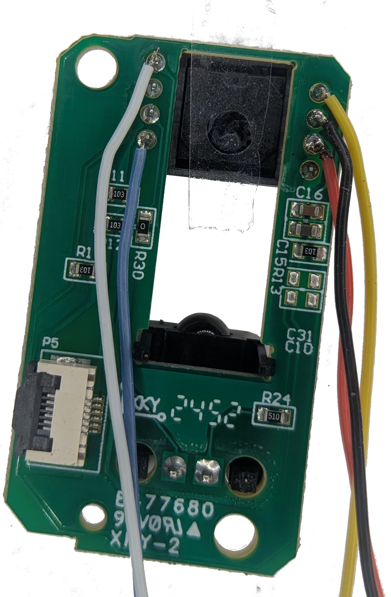
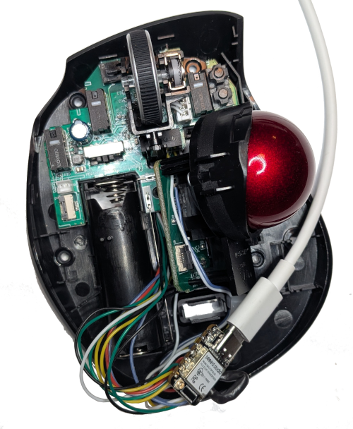
On the left is a close up of the PMW3320DB-TYDU sensor assembly. I needed to remove the trackball housing to get at the through pins. I placed a piece of tape over the sensor hole to prevent anything getting in there while I was working on the connections.
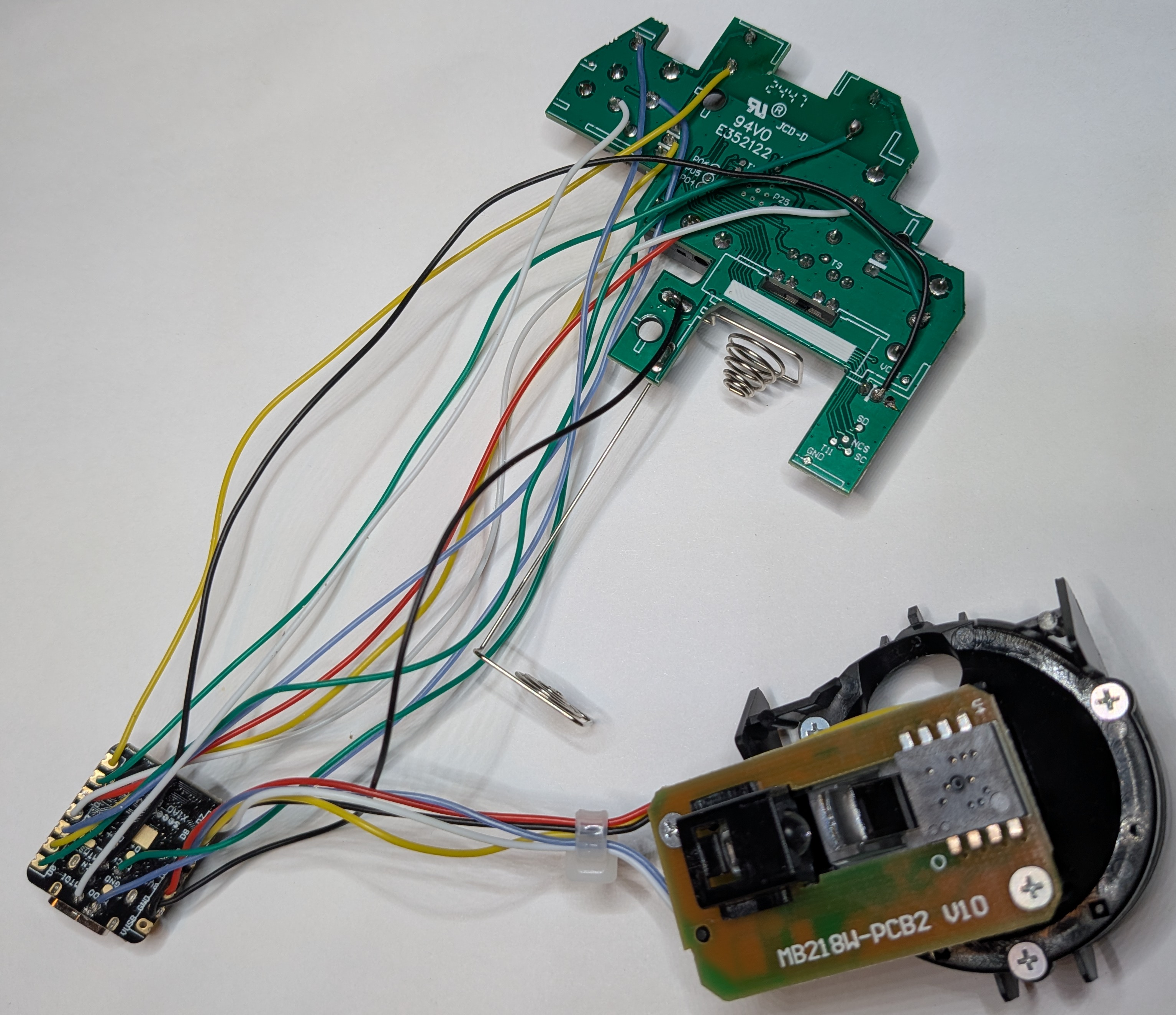
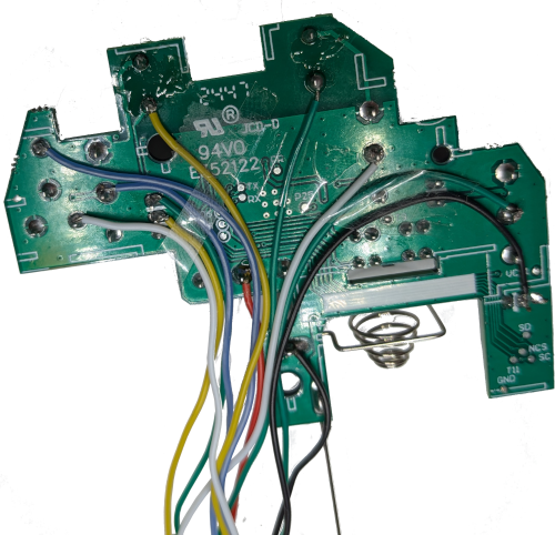
On the right is everything wired up. Notice there are some wires that curve up and round the battery terminals instead of going straight to the ESP32S3. Before soldering many of the wires, I placed the board in the EX-G case to see how the wires would best route.
One of the things I realized after I soldered all the wires on, is that the limited room under the circuit board when installed means that I need to be sure the wires are flat and don’t overlap. I ended up fiddling with this for a bit and put some tape over them to keep them in position.
If I had only wired up the three main click buttons and the scroll wheel, the wire routing would have been much easier.
Testing out the Final Assembly
With everything wired up it’s now time to test it out. Uploading the code from my ex-g GitHub repository into the ESP32S3 I want to test out:
- trackball motion
- scroll wheel scrolling
- left click
- right click
- middle click
Trackball motion is odd. The mouse cursor quickly moves to the top of my monitor and stays there. I can get the cursor to move left or right, but it just stays at the top of the monitor. I’ll revisit motion. I want to see if the other functions behave.
Rolling the scroll wheel towards me scrolls web pages down. Scrolling away scrolls them up. I didn’t recall which wire was which when I wired it up. I got lucky that they happened to be correct. I wasn’t too worried as I could change which pin is which in the code if needed.
Checking the three buttons, left, right and middle. These all perform as expected.
Back to the misbehaving motion sensor. First thing, double check it’s wired up correctly, and the resistor isn’t making contact with something metal. It all looks good.
The next step is to go back to serial print statements and see what’s happening.
First I’ll comment out all of the Mouse and USB calls in the ex-g.ino
sketch. Then add print statements for the motion values.
  if (motion || scroll) {
    auto m = motion.value_or(Motion{0, 0});
    // Mouse.move(m.delta_x, m.delta_y, scroll.value_or(0));
    Serial.print("Delta x: ");
    Serial.print(x);
    Serial.print(", Delta y: ");
    Serial.println(y);
  }
Compile and upload the code. Testing it out it’s printing normal looking values.
Delta x: 1, Delta y: 0
Delta x: 0, Delta y: -1
Delta x: 0, Delta y: -1
Delta x: -1, Delta y: 1
Delta x: 0, Delta y: -1
Nothing that looks like it would make it climb to the top of the screen and stay there. Time to revert the serial print, bring back the old code and try to capture the behavior in more detail.
Running the original code again and the cursor tracks just fine. That’s a bit of a head scratcher. Perhaps plugging it in is having an effect on the behavior. Unplug and plug back in, and the odd behavior is back. Well that’s something, even if it is intermittent. I think I’ll ask the new AI overlords if they have an idea on why this would be intermittently tracking odd based on plugging and unplugging. AI comes back suggesting that the burst read might be an issue and it might not be initializing correctly. It suggests to change the MotionSensor.cpp code to read one register at a time.
std::optional<Motion> MotionSensor::motion() {
  uint8_t motion_reg = read(MOTION);
  if (motion_reg & 0x80) {
    int8_t delta_x = (int8_t)read(DELTA_X);
    int8_t delta_y = (int8_t)read(DELTA_Y);
    return Motion{delta_x, delta_y};
  }
  return std::nullopt;
}
Why not? I don’t have a better idea at this point. Test this code out and the trackball behaves correctly. Let’s try turning it off and on again a few times to ensure it continues to function correctly. It does!
While I like the idea of the burst read to be as fast as possible, at the end of the day single register reads are probably much faster than I’ll ever notice. So I will favor a working solution over an imperceptibly faster solution.
The cursor moves proportionally to the trackball movement in every direction, but it doesn’t actually move in the expected directions. The trackball directions should be the same as a mouse, if one were to tilt the trackball so that the most exposed portion of the trackball is toward the ceiling. This means when the trackball is spun away from the operator, the cursor should move up the screen. Instead it’s moving to the right. When the trackball is spun counterclockwise, from the perspective of the operator, the cursor should move left across the screen. Instead it’s moving up the screen. I could try to figure out a different value for the AXIS_CONTROL register, but I think I’m better off modifying the way the x and y values are being interpreted.
std::optional<Motion> MotionSensor::motion() {
  uint8_t motion_reg = read(MOTION);
  if (motion_reg & 0x80) {
    // We invert these to get them to be correct on the output
    int8_t delta_y = (int8_t)read(DELTA_X);
    int8_t delta_x = -(int8_t)read(DELTA_Y);
    return Motion{delta_x, delta_y};
  }
  return std::nullopt;
}
That’s not too bad for a first test run! The only problems after wiring everything up and testing it out as one assembly was to change how the delta registers were being read and doing a (negative) 90 degree rotation of the motion values.
Reassembling the EX-G
I don’t see a good place to feed a wire through the case. Most wired mice and trackballs have the wire come out the front. The only place I see from the front would likely go through one of the scroll wheel stands. I don’t want to risk damaging that. I also think it would require a USB cable with just wires on the end instead of a plug. It may be possible to cut the plug off the end of the USB cable and then solder the USB cable wires directly to the ESP32S3. However, with my failure to remove the EX-G micro-controller and the resultant damage, I think trying to remove the USB socket from the ESP32S3 would not end well. This means that I’ll need to find a way to have the ESP32S3 connected to a USB cable plug while inside the EX-G case. Near the bottom right of the EX-G there looks to be a tall enough edge that, after some work with a Dremel, it could accommodate a USB cable.
The ESP32S3 connected to a USB cable results in doubling its length. Finding room in the EX-G case isn’t going to be easy. There looks to be room between the battery compartment and the PMW3320DB-TYDU assembly, but a standoff in the EX-G top prevents assembly. There looks to be some room on the other side of the battery compartment. Again there is a standoff in the EX-G top that gets in the way. Not sure why I was trying to save it, but I think I’m going to need to Dremel into the battery compartment.
It took me three tries and a lot of holding my mouth just right while trying to close the EX-G case, but I’ve succeeded!
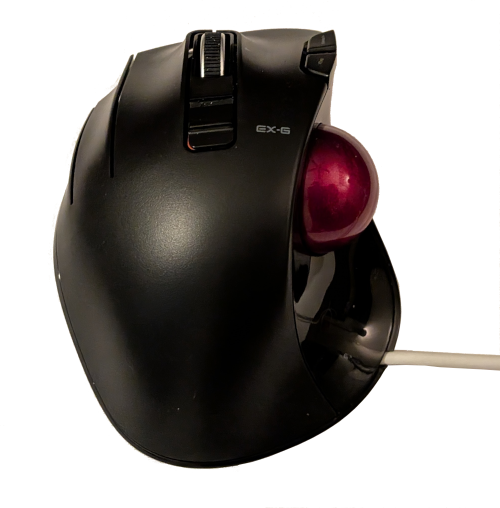
I need to test and make sure I didn’t accidentally damage a wire or connection in my efforts. Repeating the test I did earlier, all three buttons, scroll wheel and trackball function!
Using the EX-G for a Day
(The next day)
I’m excited to start work with the EX-G trackball back on the left side of my keyboard. It seems to be working okay, though I’m a bit rusty with my left thumb.
I notice that it’s hard to do precise movements. I figure this is me just being out of practice with my left hand.
An hour or so into working and I’m starting to get frustrated. Time to focus in on the fine movement behavior. Moving the cursor slowly right works fine. Moving the cursor slowly down works fine. Moving the cursor slowly left, it doesn’t move. I can move it in big jumps just fine, but if I try to do precise movement left it kind of wiggles but more or less stays in place. The same thing happens for fine movement up.
I’m a bit stumped. Fine movement right or down is alright, but up and left is almost no response. Knowing that there is a problem I decide I should keep doing what people pay me for and worry about it later.
It’s now around lunch time, I thought I could power through the lack of fine movement up and left until the end of the day, but it’s gnawing at me.
I tried to spell gnawing as “knawing”. Why does it matter which silent letter I use?
Thinking back to what the AI overlords said about the burst read not being initialized correctly got me thinking.
The desired burst read for my implementation is:
MOTIONDELTA_XDELTA_Y
When MOTION has the most significant bit (MSB) set, 0x80, then trackball
motion has occurred and the values read from DELTA_X and DELTA_Y are valid.
The code in MotionSensor.cpp is initializing
BURST_READ_FIRST
to be the MOTION register. By default the BURST_READ_FIRST is DELTA_X. If
the BURST_READ_FIRST doesn’t get initialized correctly, and stays the default,
then the first byte read would be DELTA_X. For the following explanation let’s
assume the BURST_READ_FIRST is stuck on DELTA_X.
If there has been positive x motion then the value read will likely be 0x01.
The MSB is not set, so MotionSensor.cpp will think no motion has happened. If
negative motion along the x axis occurs the value read will likely be 0xFF.
This does have the MSB set. The next byte read will be the DELTA_Y. It’s
likely to be -1, 0, or 1. However, MotionSensor.cpp will be storing this in
the delta_x position. The third byte read will be SQUAL.
The PMW3320DB-TYDU datasheet doesn’t have any information on SQUAL, but the
ADNS-3050
datasheet does. It says that SQUAL is surface quality. The range of values is
0-128. It shows an example where a sensor over a white piece of paper has a
value at around 30. Since the sensor is pointing to the trackball with a cradle
it’s probably a safe assumption this value will be in the range 30-128.
Piecing this all together, if the BURST_READ_FIRST is defaulting to DELTA_X
then:
MotionSensor.cppwill think there’s motion anytime there is a negative x value.MotionSensor.cppwill use the y value as the x valueMotionSensor.cppwill use theSQUALvalue as the y value. This will be a larger value of 30 to 128
This seems to explain the behavior, the cursor would quickly climb to the top of the screen and stay there. The cursor could be moved left and right by reasonable amounts. Recall this behavior was observed prior to the rotation of the x and y directions by 90 degrees.
With this newfound understanding of what may have been going wrong in burst
mode, and not understanding why fine grained left and up aren’t working. It’s
time to try an experiment. As the AI overlord said it could be an initialization
issue. What if the issue is that the PMW3320DB-TYDU sensor hasn’t fully powered
up by the time the setup() function in the ex-g.ino sketch tries to
initialize the PMW3320DB-TYDU?
It’s pretty easy to find out. First revert MotionSensor.cpp to burst read,
with the rotated x and y values:
std::optional<Motion> MotionSensor::motion() {
  uint8_t motion_reg;
  int8_t delta_x;
  int8_t delta_y;
  {
    SpiTransaction transaction(_cs, _settings);
    SPI.transfer(BURST_MOTION);
    delayMicroseconds(tWus);
    motion_reg = SPI.transfer(IDLE_READ);
    delayMicroseconds(tWus);
    delta_y = (int8_t)SPI.transfer(IDLE_READ);
    delayMicroseconds(tWus);
    delta_x = -(int8_t)SPI.transfer(IDLE_READ);
    delayMicroseconds(tWus);
  }
  if (motion_reg & 0x80) {
    return Motion{delta_x, delta_y};
  }
  return std::nullopt;
}
Then add a delay for 1 second prior to all other behavior in setup():
void setup() {
  serialUploadMode = checkSerialUploadMode();
  if (serialUploadMode) {
    return;
  }
  delay(1000);

  Mouse.begin();
  USB.begin();
  // D8, D9, D10 are SPI pins
  sensor.emplace(D7, 1500);
  scrollWheel.emplace(D0, D1);
  for (auto &mb : mouseButtons) {
    mb.button.emplace(mb.pin);
  }
}
Cross fingers and see what happens. It works!! I have fine grained control in all directions.
Another thing I notice is that I don’t need to unplug and plug back in after uploading the code. In Seeed Studio XIAO ESP32S3 Trackball Motion I had run into odd trackball behavior and thought it was due to needing to do a power reset of the serial bus, but it was likely this issue presenting itself.
I imagine that 1 second is a longer delay than necessary. It’s working for now and it’s a small wait in human time. Since this is a wired mouse it’s likely to get power when my computer powers on and I won’t be able to use the computer within a second so it’s an acceptable delay for me.